
Pre-script (dated 26 June 2020): This post has become less relevant (even irrelevant, perhaps) because my views on all things quantum-mechanical have evolved significantly as a result of my progression towards a more complete realist (classical) interpretation of quantum physics. I keep blog posts like these mainly because I want to keep track of where I came from. I might review them one day, but I currently don’t have the time or energy for it. 🙂
Original post:
Thermodynamics is not an easy topic, but one can’t avoid it in physics. The main obstacle, probably, is that we very much like to think in terms of dependent and independent variables. While that approach is still valid in thermodynamics, it is more complicated, because it is often not quite clear what the dependent and independent variables are. We’ve got a lot of quantities in thermodynamics indeed: volume, pressure, internal energy, temperature and – soon to be defined – entropy, which are all some function of each other. Hence, the math involves partial derivatives and other subtleties. Let’s try to get through the basics.
Volume, pressure, temperature and the ideal gas law
We all know what a volume is. That’s an unambiguous quantity. Pressure and temperature are not so unambiguous. In fact, as far as I am concerned, the key to understanding thermodynamics is to be able to not only distinguish but also relate pressure and temperature.
The pressure of a gas or a liquid (P) is the force, per unit area, exerted by the atoms or molecules in that gas or liquid as they hit a surface, such as a piston, or the wall of the body that contains it. Hence, pressure is expressed in newton per square meter: 1 pascal (Pa) = 1 N/m2. It’s a small unit for daily use: the standard atmospheric pressure is 1 atm = 101,325 Pa = 1.01325×10⁵ Pa = 1.01325 bar. We derived the formula for pressure in the previous post:
P = F/A = (2/3)·n·〈m·v2/2〉
This formula shows that the pressure depends on two variables:
- The density of the gas or the liquid (i.e. the number of particles per unit volume, so it’s two variables really: a number and a volume), and
- Their average kinetic energy.
Now, this average kinetic energy of the particles is nothing but the temperature (T), except that, because of historical reasons, we define temperature (expressed in degrees Kelvin) using a constant of proportionality—the Boltzmann constant k = kB. In addition, in order to get rid of that ugly 2/3 factor in our next formula, we’ll also throw in a 3/2 factor. Hence, we re-write the average kinetic energy 〈m·v2/2〉 as:
〈m·v2/2〉 = (3/2)·k·T
Now we substitute that definition into the first equation (while also noting that, if n is the number of particles in a unit volume, we will have N = n·V atoms in a volume V) to get what we want: the so-called ideal gas law, which you should remember from your high-school days:
PV = NkT
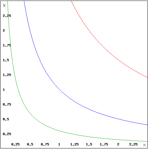
The equation implies that, for a given number of particles (for some given substance, that is), and for some given temperature, pressure and volume are inversely proportional one to another: P = NkT/V. The curve representing that relationship between P and V has the same shape as the reciprocal function y = 1/x. To be precise, it has the same shape as a rectangular hyperbola with the center at the origin, i.e. the shape of an y = m/x curve, assuming non-negative values for x and y only. The illustration below shows that graph for m = 1, 3 and 0.3 respectively. We’ll need that graph later when looking at more complicated graphs depicting processes during which we will not keep temperature constant—so that’s why I quickly throw it in here.
Of course, n·〈m·v2/2〉 is the number of atoms times the average kinetic energy of each and, therefore, it is also the internal energy of the gas. Hence, we can also write the PV = NkT equation as:
PV = (2/3)·U
We should immediately note that we’re considering an ideal gas here, so we disregard any possibility of excitation or motion inside the atoms or molecules. It matters because, if we’re decreasing the volume and, hence, increasing the pressure, we’ll be doing work, and the energy needs to go somewhere. The equation above assumes it all goes into that 〈m·v2/2〉 factor and, hence, into the temperature. Hence, it is obvious that, if were to allow for all kinds of rotational and vibratory motions inside of the atoms or molecules motions also, then the analysis would become more complicated. Having said, in my previous post I showed that the complications are limited: we can account for all kinds of internal motion by inserting another coefficient—i.e. other than 2/3. For example, Feynman calculates it as 2/7, rather than 2/3, for the diatomic oxygen molecule. That is why we usually see a much more general expression of the equation above. We will write:
PV = (γ – 1)·U
The gamma (γ) in the equation above is the rather infamous specific heat ratio, and so it’s equal to 5/3 for the ideal gas (5/3 – 1 = 2/3). I call γ infamous because its theoretical value does not match the experimental value for most gases. For example, while I just noted γ’s theoretical value for O2 (i.e. he diatomic oxygen molecule) – it’s 9/7 ≈ 1.286, because 9/7 – 1 = 2/7), the experimentally measured value for O2 is 1.399. The difference can only be explained using quantum mechanics, which is obviously not the topic of this post, and so we won’t write much about γ. However, I need to say one or two things about it—which I’ll do by showing how we could possibly measure it. Let me reproduce the illustration in my previous post here.
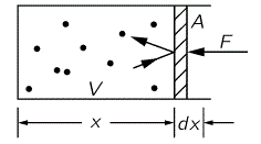 The pressure is the force per unit area (P = F/A and, hence, F = P·A), and compressing the gas amounts to applying a force over some (infinitesimal) distance dx. Hence, the (differential) work done is equal to dW = F·(−dx) = – P·A·dx = – P·dV, as A·dx = dV, obviously (the area A times the distance dx is the volume change). Now, all the work done goes into changing the internal energy U: there is no heat energy that’s being added or removed here, and no other losses of energy. That’s why it’s referred to as a so-called adiabatic compression, from the Greek a (not), dia (through) and bainein (to go): no heat is going through. The cylinder is thermally insulated. Hence, we write:
dU = – P·dV
This is a very simple differential equation. Note the minus sign: the volume is going to decrease while we do work by compressing the piston, thereby increasing the internal energy. [If you are clever (which, of course, you are), you’ll immediately say that, with increasing internal energy, we should also have an increase in pressure and, hence, we shouldn’t treat P as some constant. You’re right, but so we’re doing a marginal analysis only here: we’ll deal with the full thing later. As mentioned above, the complete picture involves partial derivatives and other mathematical tricks.]
Taking the total differential of U = PV/(γ – 1), we also have another equation:
dU = (P·dV + V·dP)/(γ – 1)
Hence, we have – P·dV = (P·dV + V·dP)/(γ – 1) or, rearranging the terms:
γdV/V + dP/P = 0
Assuming that γ is constant (which is true in theory but not in practice—another reason why this γ is rather infamous), we can integrate this. It gives γlnV + lnP = lnC, with lnC the constant of integration. Now we take the exponential of both sides to get that other formulation of the gas law, which you also may or may not remember from your high-school days:
PVγ = C (a constant)
So here you have the answer to the question as to how we can measure γ: the pressure times the volume to the γth power must be some constant. To be precise, for monatomic gases the pressure times the volume to the 5/3 ≈ 1.67 power must be a constant. The formula works for gases like helium, krypton and argon. However, the issue is more complicated when looking at more complex molecules. You should also note the serious limitation in this analysis: we should not think of P as a constant in the dU = – P·dV equation! But I’ll come back to this. As for now, just take note of it and move on to the next topic.
The Carnot heat engine
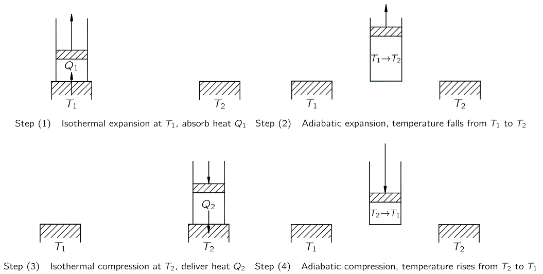
The definitions above should help us to understand and distinguish isothermal expansion and compression versus adiabatic expansion and compression which, in turn, should help us to understand what the Carnot cycle is all about. We’re looking at a so-called reversible engine here: there is no friction, and we also assume heat flows ‘frictionless’. The cycle is illustrated below: this so-called heat engine takes an amount of heat (Q1) from a high temperature (T1) heat pad (often referred to as the furnace or the boiler or, more generally, the heat source) and uses it to make some body (i.e. a piston in a cylinder in Carnot’s example) do some work, with some other amount of heat (Q2) goes back into some cold sink (usually referred to as the condenser), which is nothing but a second pad at much lower temperature (T2).

The four steps involved are the following:
(1) Isothermal expansion: The gas absorbs heat and expands while keeping the same temperature (T1). As the number of gas atoms or molecules, and their temperature, stays the same, the heat does work, as the gas expands and pushes the piston upwards. So that’s isothermal expansion. The next is different.
(2) Adiabatic expansion: The cylinder and piston are now removed from the heat pad, and the gas continues to expand, thereby doing even more work by pushing the piston further upwards. However, as the piston and cylinder are assumed to be thermally insulated, they neither gain nor lose heat. So it is the gas that loses internal energy: its temperature drops. So the gas cools. How much? It depends on the temperature of the condenser, i.e. T2, or – if there’s no condenser – the temperature of the surroundings. Whatever, the temperature cannot fall below T2.
(3) Isothermal compression: Now we (or the surroundings) will be doing work on the gas (as opposed to the gas doing work on its surroundings). The piston is being pushed back, and so the gas is slowly being compressed while, importantly, keeping it at the same temperature T2. Therefore, it delivers, through the head pad, a heat amount Q2 to the second heat reservoir (i.e. the condenser).
(4) Adiabatic compression: We take the cylinder off the heat pad and continue to compress it, without letting any heat flow out this time around. Hence, the temperature must rise, back to T1. At that point, we can put it back on the first heat pad, and start the Carnot cycle all over again.
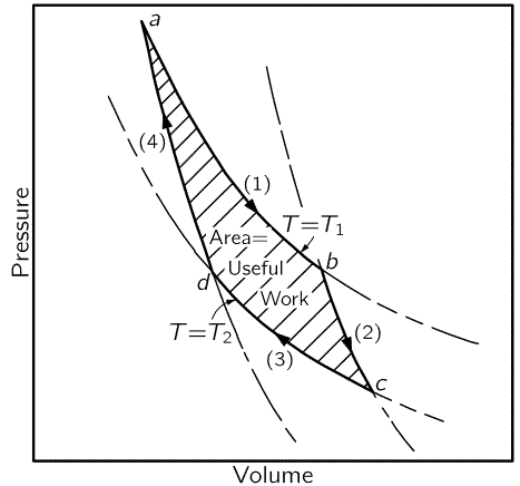
The graph below shows the relationship between P and V, and temperature (T), as we move through this cycle. For each cycle, we put in Q1 at temperature T1, and take out Q2 at temperature T2, and then the gas does some work, some net work, or useful work as it’s labeled below.
Let’s go step by step once again:
- Isothermal expansion: Our engine takes in Q1 at temperature T1 from the heat source (isothermal expansion), as we move along line segment (1) from point a to point b on the graph above: the pressure drops, the volume increases, but the temperature stays the same.
- Adiabatic expansion: We take the cylinder off the heat path and continue to let the gas expand. Hence, it continues to push the piston, and we move along line segment (2) from point b to c: the pressure further drops, and the volume further increases, but the temperature drops too—from T1 to T2 to be precise.
- Isothermal compression: Now we bring the cylinder in touch with the T2 reservoir (the condenser or cold sink) and we now compress the gas (so we do work on the gas, instead of letting the gas do work on its surroundings). As we compress the gas, we reduce the volume and increase the pressure, moving along line segment (3) from c to d, while the temperature of the gas stays at T2.
- Adiabatic compression: Finally, we take the cylinder of the cold sink, but we further compress the gas. As its volume further decreases, its pressure and, importantly, its temperature too rises, from T2 to T1 – so we move along line segment 4 from d to a – and then we put it back on the heat source to start another cycle.
We could also reverse the cycle. In that case, the steps would be the following:
- Our engine would first take in Q2 at temperature T2 (isothermal expansion). We move along line segment (3) here but in the opposite direction: from d to c.
- Then we would push the piston to compress the gas (so we’d be doing some work on the gas, rather than have the gas do work on its surroundings) so as to increase the temperature from T2 to T1 (adiabatic compression). On the graph, we go from c to b along line segment (2).
- Then we would bring the cylinder in touch with the T1 reservoir and further compress the gas so an amount of heat equal to Q1 is being delivered to the boiler at (the higher) temperature T1 (isothermal compression). So we move along line segment (1) from b to a.
- Finally, we would let the gas expand, adiabatically, so the temperature drops, back to T2 (line segment (4), from a to d), so we can put it back on the T2 reservoir, on which we will let it further expand to take in Q2 again.
It’s interesting to note that the only reason why we can get the machine to do some net work (or why, in the reverse case, we are able to transfer heat by putting some work into some machine) is that there is some mechanism here that allows the machine to take in and transfer heat through isothermal expansion and compression. If we would only have adiabatic expansion and compression, then we’d just be going back and forth between temperature T1 and T2 without getting any net work out of the engine. The shaded area in the graph above then collapses into a line. That is why actual steam engines are very complicated and involve valves and other engineering tricks, such as multiple expansion. Also note that we need two heat reservoirs: we can imagine isothermal expansion and compression using one heat reservoir only but then the engine would also not be doing any net work that is useful to us.
Let’s analyze the work that’s being doing during such Carnot cycle somewhat more in detail.
The work done when compressing a gas, or the work done by a gas as it expands, is an integral. I won’t explain in too much detail here but just remind you of that dW = F·(−dx) = – P·A·dx = – P·dV formula. From this, it’s easy to see that the integral is ∫ PdV.
An integral is an area under a curve: just substitute P for y = f(x) and V for x, and think of ∫ f(x)dx = ∫ y dx. So the area under each of the numbered curves is the work done by or on the gas in the corresponding step. Hence, the net work done (i.e. the so-called useful work) is the shaded area of the picture.
So what is it exactly?
Well… Assuming there are no other losses, the work done should, of course, be equal to the difference in the heat that was put in, and the heat that was taken out, so we write:
W = Q1 – Q2
So that’s key to understanding it all: an efficient (Carnot) heat engine is one that converts all of the heat energy (i.e. Q1 – Q2) into useful work or, conversely, which converts all of the work done on the gas into heat energy.
Schematically, Carnot’s reversible heat engine is represented as follows:

So what? You may we’ve got it all now, and that there’s nothing to add to the topic. But that’s not the case. No. We will want to know more about the exact relationship between Q1, Q2, T1 and T2. Why? Because we want to be able to answer the very same questions Sadi Carnot wanted to answer, like whether or not the engine could be made more efficient by using another liquid or gas. Indeed, as a young military engineer, fascinated by the steam engines that had – by then – become quite common, Carnot wanted to find an unambiguous answer to two questions:
- How much work can we get out of a heat source? Can all heat be used to do useful work?
- Could we improve heat engines by replacing the steam with some other working fluid or gas?
These questions obviously make sense, especially in regard to the relatively limited efficiency of steam engines. Indeed, the actual efficiency of the best steam engines at the time was only 10 to 20 percent, and that’s under favorable conditions!
Sadi Carnot attempted to answer these in a memoir, published as a popular work in 1824 when he was only 28 years old. It was entitled Réflexions sur la Puissance Motrice du Feu (Reflections on the Motive Power of Fire). Let’s see if we can make sense of it using more modern and common language. [As for Carnot’s young age, like so many, he was not destined to live long: he was interned in a private asylum in 1832 suffering from ‘mania’ and ‘general delirium’, and died of cholera shortly after, aged 36.]
Carnot’s Theorem
You may think that both questions have easy answers. The first question is, obviously, related to the principle of conservation of energy. So… Well… If we’d be able to build a frictionless Carnot engine, including a ‘frictionless’ heat transfer mechanism, then, yes, we’d be able to convert all heat energy into useful work. But that’s an ideal only.
The second question is more difficult. The formal answer is the following: if an engine is reversible, then it makes no difference how it is designed. In other words, the amount of work that we’ll get out of a reversible Carnot heat engine as it absorbs a given amount of heat (Q1) at temperature T1 and delivers some other amount of heat (Q2) at some other temperature T2 does not depend on the design of the machine. More formally, Carnot’s Theorem can be expressed as follows:
- All reversible engines operating between the same heat reservoirs are equally efficient.
- No actual engine operating between two heat reservoirs can be more efficient than a Carnot engine operating between the same reservoirs.
Feynman sort of ‘proves’ this Theorem from what he refers to as Carnot’s postulate. However, I feel his ‘proof’ is not a real proof, because Carnot’s postulate is too closely related to the Theorem, and so I feel he’s basically proving something using the result of the proof! However, in order to be complete, I did reproduce Feynman’s ‘proof’ of Carnot’s Theorem in the post scriptum to this post.
So… That’s it. What’s left to do is to actually calculate the efficiency of an ideal reversible Carnot heat engine, so let’s do that now. In fact, the calculation below is much more of a real proof of Carnot’s Theorem and, hence, I’d recommend you go through it.
The efficiency of an ideal engine
Above, I said I would need the result that PVγ is equal to some constant. We do, in the following proof that, for an ideal engine, the following relationship holds, always, for any Q1, Q2, T1 and T2:
Q1/T1 = Q2/T2
Now, we still don’t have the efficiency with this. The efficiency of an ideal engine is the ratio of the amount of work done and the amount of heat it takes in:
Efficiency = W/Q1
But W is equal to Q1 – Q2. Hence, re-writing the equation with the two heat/temperature ratios above as Q2 = (T2 /T1)·Q1, we get: W = Q1(1 – T2 /T1) = Q1(T1 – T2 )/T1. The grand result is:
Efficiency = W/Q1 = (T1 – T2 )/T1
Let me help you to interpret this result by inserting a graph for T1 going from zero to 20 degrees, and for T2 set at 0.3, 1 and 4 degrees respectively.
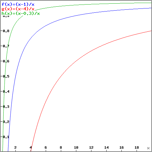
The graph makes it clear we need some kind of gauge so as to be able to actually compare the efficiency of ideal engines. I’ll come back to that in my next post. However, in the meanwhile, please note that the result makes sense: T1 needs to be higher than T2 for the efficiency to be positive (of course, we can interpret negative values for the efficiency just as well, as they imply we need to do work on the engine, rather than the engine doing work for us), and the efficiency is always less than unity, getting closer to one as the working temperature of the engine goes up.
Where does the power go?
So we have an engine that does useful work – so it works, literally – and we know where it gets its energy for that: it takes in more heat than it returns. But where is the work going? It is used to do something else, of course—like moving a car. Now how does that work, exactly? The gas exerts a force on the piston, thereby giving it an acceleration a = F/m, in accordance with Newton’s Law: F = m·a.
That’s all great. But then we need to re-compress the gas and, therefore, we need to (a) decelerate the piston, (b) reverse its direction and (c) push it back in. So that should cancel all of the work, shouldn’t it?
Well… No.
Let’s look at the Carnot cycle once more to show why. The illustrations below reproduce the basic steps in the cycle and the diagram relating pressure, volume and temperature for each of the four steps once more.
Above, I wrote that the only reason why we can get the machine to do some net work (or why, in the reverse case, we are able to transfer heat from lower to higher temperature by doing some (net) work on it) is that there is some mechanism here that allows the machine to take in and transfer heat through isothermal expansion and compression and that, if we would only have adiabatic expansion and compression, then we’d just be going back and forth between temperature T1 and T2 without getting any net work out of the engine.
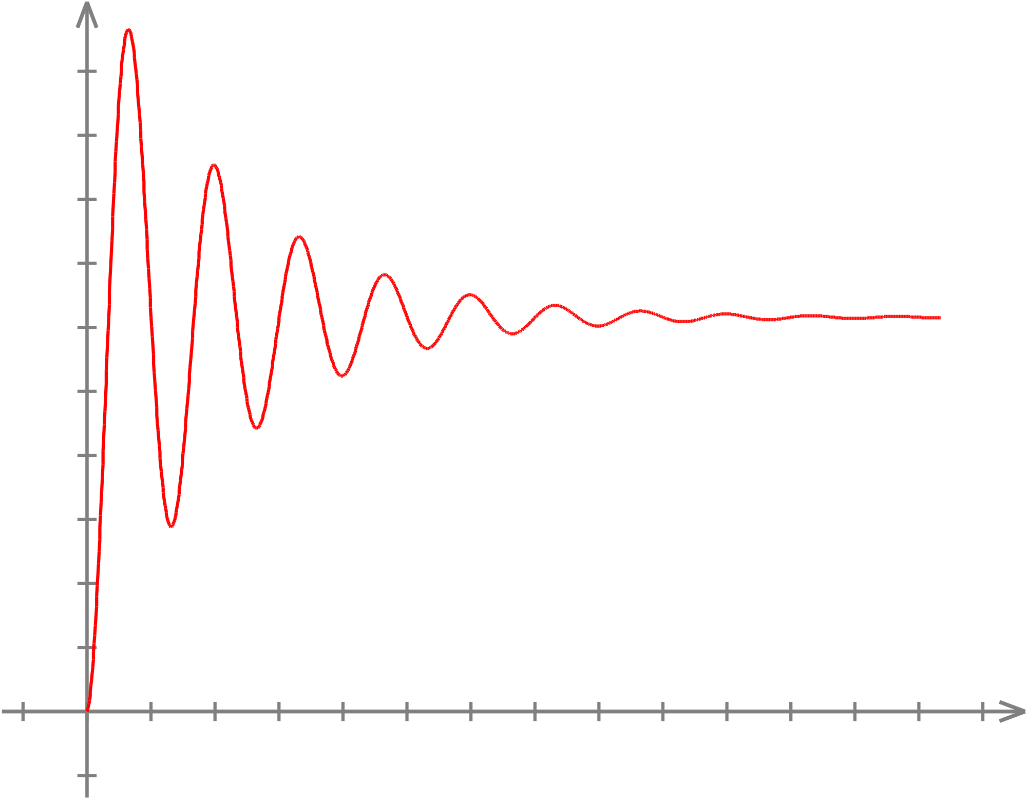
Now, that’s correct and incorrect at the same time. Just imagine a cylinder and a piston in equilibrium, i.e. the pressure on the inside and the outside of the piston are the same. Then we could push it in a bit but, as soon as we release, it would come back to its equilibrium situation. In fact, as we assume the piston can move in and out without any friction whatsoever, we’d probably have a transient response before the piston settles back into the steady state position (see below). Hence, we’d be moving back and forth on segment (2), or segment (4), in that P-V-T diagram above.
The point is: segment (2) and segment (4) are not the same: points a and b, and points c and d, are marked by the same temperature (T1 and T2 respectively) butpressure and volume is very different. Why? Because we had a step in-between step (2) and (4): isothermal compression, which reduced the volume, i.e. step (3). Hence, the area underneath these two segments is different too. Indeed, you’ll remember we can write dW = F·(−dx) = – P·A·dx = – P·dV and, hence, the work done (or put in) during each step of the cycle is equal to the integral ∫ PdV, so that’s the area under each of the line segments. So it’s not like these two steps do not contribute to the net work that’s being done through the cycle. They do. Likewise, step (1) and (3) are not each other’s mirror image: they too take place at different volume and pressure, but that’s easier to see because they take place at different temperature and involve different amounts of heat (Q1 and Q2 respectively).
But, again, what happens to the work? When everything is said and done, the piston does move up and down over the same distance in each cycle, and we know that work is force times distance. Hence, if the distance is the same… Yes. You’re right: the piston must exert some net force on something or, to put it differently, the energy W = Q1 − Q2 must go somewhere. Now that’s where the time variable comes in, which we’ve neglected so far.
Let’s assume we connect the piston to a flywheel, as illustrated below, there had better be some friction on it because, if not, the flywheel would spin faster and faster and, eventually, spin out of control and all would break down. Indeed, each cycle would transfer additional kinetic energy to the flywheel. When talking work and kinetic energy, one usually applies the following formula: W = Q1 and Q2 = Δ[mv2/2] = [mv2/2]after − [mv2/2]before. However, we’re talking rotational kinetic energy so we should use the rotational equivalent for mv2/2, which is Iω2/2, in which I is the moment of inertia of the mass about the center of rotation and ω is the angular velocity.
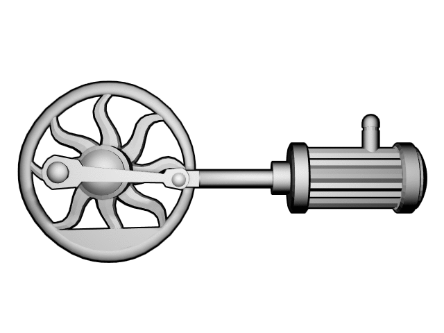
You get the point. As we’re talking time now, we should also remind you of the concept of power. Power is the amount of work or energy being delivered, or consumed, per unit of time (i.e. per second). So we can write it as P(t) = dW/dt. For linear motion, P(t) can be written as the vector product (I mean the scalar, inner or dot product here) of the force and velocity vectors, so P(t) = F·v. Again, when rotation is involved, we’ve got an equivalent formula: P(t) = τ·ω, in which τ represents the torque and ω is, once again, the angular velocity of the flywheel. Again, we’d better ensure some load is placed on the engine, otherwise it will spin out of control as vand/or ω get higher and higher and, hence, the power involved gets higher and higher too, until all breaks down.
So… Now you know it all. 🙂
Post scriptum: The analysis of the Carnot cycle involves some subtleties which I left out. For example, you may wonder why the gas would actually expand isothermically in the first step of the Carnot cycle. Indeed, if it’s at the same temperature T1 as the heat source, there should be no heat flow between the heat pad and the gas and, hence, no gas expansion, no? Well… No. 🙂 The gas particles pound on every wall, but only the piston can move. As the piston moves out, frictionless, inside of the cylinder, kinetic energy is being transferred from the gas particles to the piston and, hence, the gas temperature will want to drop—but then that temperature drop will immediately cause a heat transfer. That’s why the description of a Carnot engine also postulates ‘frictionless’ heat transfer.
In fact, I note that Feynman himself struggles a bit to correctly describe what’s going on here, as his description of the Carnot cycle suggests some active involvement is needed to make the piston move and ensure the temperature does not drop too fast. Indeed, he actually writes following: “If we pull the piston out too fast, the temperature of the gas will fall too much below T and then the process will not quite be reversible.” This sounds, and actually is, a bit nonsensical: no pulling is needed, as the gas does all of the work while pushing the piston and, while it does, its temperature tends to drop, so it will suck it heat in order to equalize its temperature with its surroundings (i.e. the heat source). The situation is, effectively, similar to that of a can with compressed air: we can let the air expand, and thereby we let it do some work. However, the air will not re-compress itself by itself. To re-compress the air, you’ll need to apply the same force (or pressure I should say) but in the reverse direction.
Finally, I promised I would reproduce Feynman’s ‘proof’ of Carnot’s Theorem. This ‘proof’ involves the following imaginary set-up (see below): we’ve got engines, A and B. We assume A is an ideal reversible engine, while B may or may not be reversible. We don’t care about its design. We just assume that both can do work by taking a certain amount of heat out of one reservoir and putting another amount of heat back into another reservoir. In fact, in this set-up, we assume both engines share a large enough reservoir so as to be able to transfer heat through that reservoir.
Engine A can take an amount of heat equal to Q1 at temperature T1 from the first reservoir, do an amount of work equal to W, and then deliver an amount of heat equal to Q2 = Q1 – W at temperature T2 to the second reservoir. However, because it’s a reversible machine, it can also go the other way around, i.e. it can take Q2 = Q1 – W from the second reservoir, have the surroundings do an amount of work W on it, and then deliver Q1 = Q2 + W at temperature T1. We know that engine B can do the same, except that, because it’s different, the work might be different as well, so we’ll denote it by W’.
Now, let us suppose that the design of engine B is, somehow, more efficient, so we can get more work out of B for the same Q1 and the same temperatures T1 and T2. What we’re saying, then, is that W’ – W is some positive non-zero amount. If that would be true, we could combine both machines. Indeed, we could have engine B take Q1 from the reservoir at temperature T1, do an amount of work equal to W on engine A so it delivers the same amount Q1 back to the reservoir at the same temperature T1, and we’d still be left with some positive amount of useful work W’ – W. In fact, because the amount of heat in the first reservoir is restored (in each cycle, we take Q1 out but we also put the same amount of heat back in), we could include it as part of the machine. It would no longer need to be some huge external thing with unlimited heat capacity.
So it’s great! Each cycle gives us an amount of useful work equal to W’ – W. What about the energy conservation law? Well… engine A takes Q1 – W from the reservoir at temperature T2, and engine B gives Q1 – W’ back to it, so we’re taking a net amount of heat equal to (Q1 – W) – (Q1 – W’) = W’ – W out of the T2 reservoir. So that works out too! So we’ve got a combined machine converting thermal energy into useful work. It looks like a nice set-up, doesn’t it?
Yes. The problem is that, according to Feynman, it cannot work. Why not? Because it violates Carnot’s postulate. The reasoning here is not easy. Let’s me try to do my best to present the argument correctly. What’s the problem? The problem is that we’ve got an engine here that operates at one temperature only. Now, according to Carnot’s postulate, it is not possible to extract the energy of heat at a single temperature with no other change in the system or the surroundings. Why not? Feynman gives the example of the can with compressed air. Imagine a can of compressed air indeed, and imagine we let the air expand, to drive a piston, for example. Now, we can imagine that our can with compressed air was in touch with a large heat reservoir at the same temperature, so its temperature doesn’t drop. So we’ve done work with that can at a single temperature. However, this doesn’t violate Carnot’s postulate because we’ve also changed the system: the air has expanded. It would only violate Carnot’s postulate if we’d find a way to put the air back in using exactly the same amount of work, so the process would be fully reversible. Now, Carnot’s postulate says that’s not possible at the same temperature. If the whole world is at the same temperature, then it is not possible to reversibly extract and convert heat energy into work.
I am not sure the example of the can with compressed air helps, but Feynman obviously thinks it should. He then phrases Carnot’s postulate as follows: “It is not possible to obtain useful work from a reservoir at a single temperature with no other changes.” He therefore claims that the combined machine as described above cannot exist. Ergo, W’ cannot be greater than W. Switching the role of A and B (so B becomes reversible too now), he concludes that W can also not be greater than W’. Hence, W and W’ have to be equal.
Hmm… I know that both philosophers and engineers have worked tirelessly to try to disprove Carnot’s postulate, and that they all failed. Hence, I don’t want to try to disprove Carnot’s postulate. In fact, I don’t doubt its truth at all. All that I am saying here is that I do have my doubts on the logical rigor of Feynman’s ‘proof’. It’s like… Well… It’s just a bit too tautological I’d say.
Some content on this page was disabled on June 17, 2020 as a result of a DMCA takedown notice from Michael A. Gottlieb, Rudolf Pfeiffer, and The California Institute of Technology. You can learn more about the DMCA here:
https://wordpress.com/support/copyright-and-the-dmca/
Some content on this page was disabled on June 17, 2020 as a result of a DMCA takedown notice from Michael A. Gottlieb, Rudolf Pfeiffer, and The California Institute of Technology. You can learn more about the DMCA here:https://wordpress.com/support/copyright-and-the-dmca/
Some content on this page was disabled on June 17, 2020 as a result of a DMCA takedown notice from Michael A. Gottlieb, Rudolf Pfeiffer, and The California Institute of Technology. You can learn more about the DMCA here:

3 thoughts on “First Principles of Thermodynamics”