
As Feynman puts it, studying physics is not always about the ‘the great and esoteric heights’. In fact, you usually have to come down from then fairly quickly – studying physics is similar to mountain climbing in that regard 🙂 – and study ‘relatively low-level subjects’, such as electrical circuits, which is what we’ll do in this and the next post.
As I’ve introduced some key concepts in a previous post already, let me recapitulate the basics, which include the concept of the electromotive force, which is basically the voltage, i.e. the potential difference, that’s produced in a loop or coil of wire as the magnetic flux changes. I also talked about the impedance in a AC circuit. Finally, we also discussed the power and energies involved. Important results from this previous discussion include (but are not limited to):
- A constant speed AC generator will create an alternating current with the emf, i.e. the voltage, varying as V0·sin(ωt).
- If we only have resistors as circuit elements, and the resistance in the circuit adds up to R, then the electric current in the circuit will be equal to I = Ɛ/R = V/R = (V0/R)·sin(ωt). So that’s Ohm’s Law, basically.
- The power that’s produced and consumed in an AC circuit is the product of the voltage and the current, so P = Ɛ·I = V·I. We also showed this electrical power is equal to the mechanical power dW/dt that makes the generator run.
- Finally, we explained the concept of impedance (denoted by Z) using Euler’s formula: Z = |Z|eiθ, mentioning that, if other circuit elements than resistors are involved, such as inductors, then it’s quite likely that the current signal will lag the voltage signal, with the phase factor θ telling us by how much.
It’s now time to introduce those ‘other’ circuit elements. So let’s start with inductors here, and the concept of inductance itself. There’s a lot of stuff to them, and so let’s go over it point by point.
The concept of self-inductance
In its simplest form, an inductor is just a coil, but they come in all sizes and shapes. If you want to see how they might look like, just google some images of micro-electronic inductors, and then, just to see the range of applications, some images of inductors used for large-scale industrial applications. If you do so, you’re likely to see images of transformers too, because transformers work on the principle of mutual inductance, and so they involve two coils, i.e. two inductors.
Contrary to what you might expect, the concept of self-inductance (or inductance tout court) is quite simply: a changing current will cause a changing magnetic field and, hence, some emf. Now, it turns out that the induced emf is proportional to the change in current. So we’ve got another constant of proportionality here, so it’s like how we defined resistance, or capacitance. So, in many ways, the inductance is just another proportionality coefficient. If we denote it by L – the symbol is said to honor the Russian phyicist Heinrich Lenz, whom you know from Lenz’ Law – then we define it as:
L = −Ɛ/(dI/dt)
The dI/dt factor is, obviously, the time rate of change of the current, and the negative sign indicates that the emf opposes the change in current, so it will tend to cause an opposing current. That’s why the emf involved is often referred to as a ‘back emf’. So that’s Lenz’ Law basically. As you might expect, the physicists came up with yet another derived unit, the Henry, to honor yet another physicist, Joseph Henry, an American scientist who was a contemporary of Michael Faraday and independently discovered pretty much the same as Faraday: one henry (H) equals one volt·second per ampere: 1 H = 1 V·s/A.
The concept of mutual inductance
Feynman introduces the topic of inductance with a two-coil set-up, as shown below, noting that a current in coil 1 will induce some emf in coil 2, which he denotes by M12. Conversely, a current in coil 2 will induce some emf in coil 1, which he denoted by M21. M12 and M21 are also constants: they depend on the geometry of the coils, including the length of the solenoid (l), its surface area (S) and the number of loop turns of the coils (N1 and N2).

The next step in the analysis is then to acknowledge that each coil should also produce a ‘back emf’ in itself, which we can denote by M11 and M22 respectively, but then these constants are, of course, equal to the self-inductance of the coils so, taking into account the convention in regard to the sign of the self-inductance, we write:
L1 = − M11 and L1 = − M22
You will now wonder: what’s the total emf in each coil, taking into account that we do not only have mutual inductance but also self-inductance? Frankly, when I was a kid, and my father tried to tell me one or two things about this, it confused me very much. I could not imagine what happened in one coil, let alone in two coils. I had this vision of a current producing some ‘back-current’, and then the ‘back-current’ producing ‘back-current’ again, and so I could not imagine how one could solve this problem. So the image in my head was very much like that baking powder box which Feynman evokes when talking about the method of images to find the electric fields in situations with an easy geometry, so that’s the picture of a baking powder box which has on its label a picture of a baking powder box which has… Well… Etcetera. Unfortunately, my father didn’t push us to study math and, therefore, I knew that one could solve such problems mathematically – we’re talking a converging series here – but I did not know how, and that’s why I found it all very confusing.
Now I understand there’s one current only, and one potential difference only, and that the formulas do not involve some infinite series of terms. But… Well… I am not ashamed to say these problems are still testing the (limited) agility of my mind. The first thing to ‘get’ is that we’re talking a back emf, and so that’s not a current but a potential difference. In fact, as I explained in my post on the electromotive force, the term ‘force’ in emf is actually misleading, and may lead to that same erroneous vision that I had as a kid: forces generating counter-forces, that generate counter-forces, that generate counter-forces, etcetera. It’s not like that: we have some current – one current – in a coil and we’ll have some voltage – one voltage – across the coil. If the coil would be a resistor instead of a coil, we’d find that the ratio of this voltage and the current would be some constant R = V/I. Now here we’re talking a coil indeed, so that’s a different circuit element, and we find some other ratio, L = −V/(dI/dt) = −Ɛ/(dI/dt). Why the minus sign? Well… As said, the induced emf will be such that it will tend to counter the current, and current flows from positive to negative as per our convention.
But… Yes? So how does it work when we put this coil in some circuit, and how does the resistance of the inductor come into play? Relax. We’ve just been talking ideal circuit elements so far, and we’ve discussed only two: the resistor and the inductor. We’ll talk about voltage sources (or generators) and capacitors too, and then we’ll link all of these ideal circuit elements. In short, we’ll analyze some real-life electrical circuit soon, but first you need to understand the basics. Let me just note that an ideal inductor appears a zero-resistance conductor in a direct current (DC) circuit, so it’s a short-circuit really! Please try to mentally separate out those ‘ideal’ circuit components. Otherwise you’ll never be able to make sense of it all!
In fact, there’s a good reason why Feynman starts with explaining mutual inductance before discussing a little circuit like the one below, which has an inductor and a voltage source. The two-coil situation above is effectively easier to understand, although it may not look like that at first. So let’s analyze that two-coil situation in more detail first. In other words, let me try to understand the situation that I didn’t understand as a kid. 🙂

Because of the law of superposition, we should add fluxes and changes in fluxes and, hence, we should also add the electromotive forces, i.e. the induced voltages. So, what we have here is that the total emf in coil 2 should be written as:
Ɛ2 = M21·(dI1/dt) + M22·(dI2/dt) = M21·(dI1/dt) – L2·(dI2/dt)
What we’re saying here is that the emf, i.e. the voltage across the coil, will indeed depend on the change in current in the other coil, but also on the change in current of the coil itself. Likewise, the total emf in coil 1 should be written as:
Ɛ1 = M12·(dI2/dt) + M11·(dI1/dt) = M12·(dI2/dt) – L1·(dI1/dt)
Of course, this does reduce to the simple L = −Ɛ/(dI/dt) if there’s one coil only. But so you see where it comes from and, while we do not have some infinite series 🙂 we do have a system of two equations here, and so let me say one or two things about it.
The first thing to note is that it is not so difficult to show that M21 is equal to M12, so we can simplify and write that M21 = M12 = M. Now, while I said ‘not so difficult’, I didn’t mean it’s easy and, because I don’t want this post to become too long, I’ll refer you to Feynman for the proof of this M21 = M12 = M equation. It’s a general proof for any two coils or ‘circuits’ of arbitrary shape and it’s really worth the read. However, I have to move on.
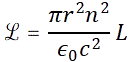
The second thing to note is that this coefficient M, which is referred to as the mutual inductance now (so singular instead of plural) depends on the ‘circuit geometry’ indeed. For a simple solenoid, Feynman calculates it as
M = −(1/ε0c2)·(N1·N2)·S/l,
with l the length of the solenoid, S its surface area (S), and N1 and N2 the respective number of loop turns of the two coils. So, yes, only ‘geometry’ comes into play. [Note that’s quite obvious from the formula because a switch of the subscripts of N1 and N2 makes no difference, of course!]. Now, it’s interesting to note that M is the same for, let’s say, N1 = 100 and N2 = 10 and for N1 = 20 and N2 = 50. In fact, because you’re familiar with what transformers do, i.e. transforming voltages, you may think that’s counter-intuitive. It’s not. The thing with the number of coils does not imply that Ɛ1 and Ɛ2 remain the same. Our set of equations is Ɛ1 = M·(dI2/dt) – L1·(dI1/dt) and Ɛ2 = M·(dI1/dt) – L2·(dI2/dt), and so L1 and L2 clearly do vary as N1 and N2 vary! So… Well… Yes. We’ve got a set of two equations with two independent variables (I1 and I2) and two dependent variables (Ɛ1 and Ɛ2). Of course, we could also phrase the problem the other way around: given two voltages, what are the currents? 🙂
Of course, that makes us think of the power that goes in and out of a transformer. Indeed, you’ll remember that power is voltage times current. So what’s going on here in regard to that?
Well… There’s a thing with transformers, or with two-coil systems like this in general, that is referred to as coupling. The geometry of the situation will determine how much flux from one coil is linked with the flux of the other coil. If most, or all of it, is linked, we say the two coils are ‘tightly coupled’ or, in the limit, that they are fully coupled. There’s a measure for that, and it’s called the coefficient of coupling. Let’s first explore that concept of power once more.
Inductance, energy and electric power
It’s easy to see that we need electric power to get some current going. Now, as we pointed out in our previous post, the power is equal to the voltage times the current. It’s also equal, of course, to the amount of work done per second, i.e. the time rate of change of the energy W, so we write:
dW/dt = Ɛ·I
Now, we defined the self-inductance as L = −Ɛ/(dI/dt) and, therefore, we know that Ɛ = −L·(dI/dt), so we have:
dW/dt = −L·I·(dI/dt)
What is this? A differential equation? Yes and no. We’ve got not one but two functions of time here, W and I, and, while their derivatives with respect to time do appear in the equation, what we need to do is just integrate the two sides over time. We get: W = −(1/2)·L·I2. Just check it by taking the time derivative of both sides. Of course, we can add any constant, to both sides in fact, but that’s just a matter of choosing some reference point. We’ll chose our constant to be zero, and also think about the energy that’s stored in the coil, i.e. U, which we define as:
U = −W = −(1/2)·L·I2
Huh? What’s going on here? Well… It’s not an easy discussion, but let’s try to make sense of it. We have some changing current in the coil here but, obviously, some kind of inertia also: the coil itself opposes the change in current through the ‘back emf’. It requires energy, or power, to overcome the inertia. We may think of applying some voltage to offset the ‘back emf’, so we may effectively think of that little circuit with an inductor and a voltage source. The voltage V we’d need to apply to offset the inertia would, obviously, be equal to the ‘back emf’, but with its sign reversed, so we have:
V = − Ɛ = L·(dI/dt)
Now, it helps to think of what a current really is: it’s about electric charges that are moving at some velocity v because some force is being applied to them. As in any system, the power that’s being delivered is the dot product of the force and the velocity vectors (that ensures we only take the tangential component of the force into account), so if we have n moving charges, the power that is being delivered to the circuit is (F·v)·n. What is F? It’s obviously, qE, as the electric field is the force per unit charge, so E = F/q. But so we’re talking some circuit here and we need to think of the power being delivered to some infinitesimal element ds in the coil, and so that’s (F·v)·n·ds, which can be written as: (F·ds)·n·v. And then we integrate over the whole coil to find: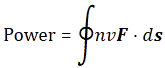
Now, you may or may not remember that the emf (Ɛ) is actually defined as the line integral ∫ E·ds line, taken around the entire coil and, hence, noting that E = F/q, and that the current I is equal to I = q·n·v, we got our power equation. Indeed, the integrand or kernel of our integral becomes F·n·v·ds = q·E·n·v·ds = I·E·ds. Hence, we get our power formula indeed: P = V·I, with V the potential difference, i.e. the voltage across the coil.
I am getting too much into the weeds here. The point is: we’ve got a full and complete analog to the concept of inertia in mechanics here: instead of some force F causing some mass m to change its velocity according to Newton’s Law, i.e. F = m·a = m·(dv/dt), we here have a potential difference V causing some current I to change according to the V = L·(dI/dt) law.
This is very confusing but, remember, the same equations must have the same solutions! So, in an electric circuit, the inductance is really like what the mass is in a mechanics. Now, in mechanics, we’ll say that our mass has some momentum p = m·v, and we’ll also say that its kinetic energy is equal to (1/2)m·v2. We can do the same for our circuit: potential energy is continuously being converted into kinetic energy which, for our inductor, we write as U = (1/2)·L·I2.
Just think about by playing with one of the many online graphing tools. The graph below, for example, assumes the current builds up to some maximum. As it reaches its maximum, the stored energy will also max out. Now, you should not worry about the units here, or the scale of the graphs. The assumption is that I builds up from 0 to 1, and that L = 1, so that makes U what it is. Using a different constant for L, and/or different units for I, will change the scale of U too, but not its general shape, and that shape gives you the general idea.
 The example above obviously assumes some direct current, so it’s a DC circuit: the current builds up, but then stabilizes at some maximum that we can find by applying Ohm’s Law to the resistance of the circuit: I = V/R. Resistance? But we were talking an ideal inductor? We are. If there’s no other resistance in the circuit, we’ll have a short-circuit, so the assumption is that we do have some resistance in the circuit and, therefore, we should also think of some energy loss to heat from the current in the resistance, but that’s not our worry here.
The illustration below is, perhaps, more interesting. Here we are, obviously, applying an alternating current, and so the current goes in one and then in the other direction, so I > 0, and then I < 0, etcetera. We’re assuming some nice sinusoidal curve for the current here (i.e. the blue curve), and so we get what we get for U (i.e. the red curve): the energy goes up and down between zero and some maximum amplitude that’s determined by the maximum current.

So, yes, it is, after all, quite intuitive: building up a current does require energy from some external source, which is used to overcome the ‘back emf’ in the inductor, and that energy is stored in the inductor itself. [If you still wonder why it’s stored in the inductor, think about the other question: where else would it be stored?] How is stored? Look at the graph and think: it’s stored as kinetic energy of the charges, obviously. That explains why the energy is zero when the current is zero, and why the energy maxes out when the current maxes out. So, yes, it all makes sense! 🙂
Let’s now get back to that coupling constant.
The coupling constant
We can apply our reasoning to two coils. Indeed, we know that Ɛ1 = M·(dI2/dt) – L1·(dI1/dt) and Ɛ2 = M·(dI1/dt) – L2·(dI2/dt). So the power in the two-coils system is dW/dt = Ɛ1·I1 + Ɛ2·I2, so we have:
dW/dt = M·I1(dI2/dt) – L1·I1·(dI1/dt) + M·I2·(dI1/dt) – L2·I2·(dI2/dt)
= – L1·I1·(dI1/dt) – L2·I2·(dI2/dt) + M·I1(dI2/dt)·I2·(dI1/dt)
Integrating both sides, and equating U with −W once more, yields:
U = (1/2)·L1·I12 + (1/2)·L2·I22 + M·I1·I2
[Again, you should just take the time derivative to verify this. If you don’t forget to apply the product rule for the M·I1·I2 term, you’ll see I am not writing too much nonsense here.] Now, there’s an interesting algebraic transformation of this expression, and an equally interesting explanation why we’d re-write the expression as we do. Let me copy it from Feynman so I’ll be using his fancier L and M symbols now. 🙂
So what? Well… Taking into account that inequality above, we can write the relation between M and the self-inductances L1 and L2 using some constant k, which varies between 0 and 1 and which we’ll refer to as the coupling constant:
![]()
We refer to k as the coupling constant, for rather obvious reasons: if it’s near zero, the mutual inductance will be very small, and if it’s near one, then the coils are said to be ‘tightly coupled’, and the ‘mutual flux linkage’ is then maximized. As you can imagine, there’s a whole body of literature out there relating this coupling constant to the behavior of transformers or other circuits where mutual inductance plays a role.
The formula for self-inductance
We gave the formula for the mutual inductance of two coils that are arranged as one solenoid on top of the other (cf. the illustration I started with):
M = −(1/ε0c2)·(N1·N2)·S/l
It’s a very easy calculation, so let me quickly copy it from Feynman:
You’ll say: where is the M here? This is a formula for the emf! It is, but M is the constant of proportionality in front, remember? So there you go. 🙂
Now, you would think that getting a formula for the self-inductance L of some solenoid would be equally straightforward. It turns out that that is not the case. Feynman needs two full pages and… Well… By now, you should now how ‘dense’ his writing really is: if it weren’t so dense, you’d be reading Feynman yourself, rather than my ‘explanations’ of him. 🙂 So… Well.. If you want to see how it works, just click on the link here and scroll down to the last two pages of his exposé on self-inductance. I’ll limit myself to just jotting down the formula he does obtain when he’s through the whole argument:
See why he uses a fancier L than ‘my’ L? ‘His’ L is the length of the solenoid. 🙂 And, yes, r is the radius of the coil and n the number of turns per unit length in the winding. Also note this formula is valid only if L >> R, so the effects at the end of the solenoid can be neglected. OK. Done. 🙂
Well… That’s it for today! I am sorry to say but the next post promises to be as boring as this one because… Well… It’s on electric circuits again. 😦
Some content on this page was disabled on June 16, 2020 as a result of a DMCA takedown notice from The California Institute of Technology. You can learn more about the DMCA here:
https://wordpress.com/support/copyright-and-the-dmca/
Some content on this page was disabled on June 16, 2020 as a result of a DMCA takedown notice from The California Institute of Technology. You can learn more about the DMCA here:https://wordpress.com/support/copyright-and-the-dmca/
Some content on this page was disabled on June 16, 2020 as a result of a DMCA takedown notice from The California Institute of Technology. You can learn more about the DMCA here:https://wordpress.com/support/copyright-and-the-dmca/
Some content on this page was disabled on June 20, 2020 as a result of a DMCA takedown notice from Michael A. Gottlieb, Rudolf Pfeiffer, and The California Institute of Technology. You can learn more about the DMCA here:

One thought on “Self-inductance, mutual inductance, and the power and energy of inductors”