
Pre-scriptum (dated 26 June 2020): This post – part of a series of rather simple posts on elementary math and physics – has suffered only a little bit from the attack by the dark force—which is good because I still like it. One illustration seems to have removed because of perceived ‘unfair use’, but you will be able to google equivalent stuff. While my views on the true nature of light, matter and the force or forces that act on them have evolved significantly as part of my explorations of a more realist (classical) explanation of quantum mechanics, I think most (if not all) of the analysis in this post remains valid and fun to read. In fact, I would dare to say the whole Universe is all about resonance phenomena!
Original post:
My previous post was too short to do justice to the topic (resonance phenomena). That’s why I’ll approach the topic using the relatively easy example of an electric oscillator. In addition, in this post I’ll also talk about the Q of an oscillator and the concept of a transient.
[…] Oh… Well… I admit there’s no real reason to write this post. It’s not essential – or not as essential as understanding something about complex numbers, for example. In fact, I admit the reason for writing this post is entirely emotional: my father was a rather distant figure, and we never got along, I guess, although he did patch things up near the end of his life–but I realize now, at the age of 45 (so that’s the age I associate with him), that we have a lot in common, including this desire to catch up with things physical and mathematical. He would not have been able to read a lot of what I am writing about in this blog, because he had gone to school only until 18 and, hence, differential equations and complex numbers must have frightened him more than they frighten me. In fact, even then, he actually might have understood something about differential equations, and perhaps something about complex numbers too. I don’t know. I should try to find the books he read. In any case, he surely did not have much of a clue about relativity theory or so. That being said, he sure knew a lot more about electric circuits than I ever will, and I guess that’s the real reason why I want to do a post on the electric oscillator here.
My father knew everything about electric motors, for example. Single-phase, split-phase, three-phase; synchronous or asynchronous; with two, four, six or eight poles; wound rotors or squirrel-cage rotors; centrifugal switches, capacitors… Electric motors (and engines in general) had no secrets for him. While I would understand the basic principle of the electric motor (he actually helped me build a little one – just using copper wire, a horsehoe magnet and a huge nail, and a piece of iron – to demonstrate in school), I had difficulty with the huge number of wires coming out of these things. [We had plenty of motors, because my father would bring old washing machines home to get the parts out.] Part of the problem was that he would never take the time to explain me how the capacitor that one needs to start a single-phase motor actually works.
Now I know, because I looked it up: single-phase electric (induction) motors have an auxiliary winding because they do not need have a starting torque. The magnetic field does not rotate: it just pulsates between 0 and 180 degrees and, hence, the rotor doesn’t know in which direction to go and, hence, if there’s no fuse to protect it, the wiring will start burning. [To explain why the wiring does not get (too) hot when it’s rotating is another story–which I won’t tell here because it involves changing electric and magnetic fields and so that’s a bit more complicated.] So now I have a bit more of an inkling of why there’s so many wires coming out of a simple (single-phase) electric motor:
- We have wires coming from the rotor (or, to be precise, from the carbon brushes). [Not always though: a lot of those old electric motors had so-called squirrel-cage rotors, instead of wound rotors.]
- We have wires going to the ‘run’ or ‘main’ winding in the stator (i.e. the stationary part of the motor).
- We have wires going to the ‘start’ or ‘auxiliary’ winding. In fact, with single phase, the ‘run’ and ‘start’ winding will share one common ‘end’ and so there will be three wires only: usually black, brown and blue in Europe and, to make things complicated, the same wires will usually be red, yellow and black in the US. 🙂
- We have wires coming from the capacitor and, most probably, also from some fuse somewhere, and then there’s a centrifugal switch to switch the auxiliary winding off once the motor is running, so that’s one or two more wires.
- And then we also need to control the speed of the motor and so that implies even more wires and little control boxes.
Phew! Things become complicated here. The primitive way to change the speed of single-phase motor is to change the number of poles. How? Well… We can separate the windings and/or by placing taps in-between. In short, more wires. A motor with two poles only will run at 3000 rpm when supplies with 50 Hz power, but we can also have 4, 6, 8 and more poles. More poles, means slower velocity. For example, if we switch to 10 poles, then the motor will run at 600 rpm (yes, 10/2 = 3000/600 = 5, so it’s the same factor). However, changing the number of poles while the motor is running is rather impractical so, in practice, speed control is done through a device referred to as a variable frequency drive (VFD). But so my father would just cut the wires and we’d end up with a motor running at one speed only–not very handy because these things spin incredibly fast–and with too many wires.
I have to admire him for making sense of all those wires. He would do so by measuring the resistance off all the circuits. So he’d just pick two wires and measure the resistance from one end to the other. For example, the main winding has less resistance–typically less than 5 Ω (Ohm)–than the auxiliary winding–typically 10 to 20 Ω (Ohm). Why? The wiring used to run the motor will typically be thicker and, hence, offer less resistance. With a bit of knowledge like that, he’d figure out the wiring in no time, while I would just sit and stare and wonder how he did it.
In any case, let me explain here what I would have liked my father to explain to me, and that’s the components of an electric circuit, and how an electric oscillator works–more or less at least.
The electric oscillator
In an electric circuit, we can have passive and active elements. An example of an active element would be a generator. That’s not passive. So what’s passive?
First, we have a resistor. A resistor is any piece of some substance through we have some current flowing and which offers resistance to that flow of electric current. What does that mean? The resistance (denoted by the symbol R) will determine the flow of current (I) through the circuit as a function of the potential difference (i.e. the voltage) V across. In fact, the resistance is defined as the factor of proportionality between V and I. So that’s Ohm’s Law really:
V = RI = R(dq/dt)
As for the current (I) being equal to I = dq/dt, that’s the definition of electric current itself: a current transports electric charge through a wire, so we can measure the current at any point in the electric current as the time-rate of change dq/dt. Current is Coulomb per second, i.e. in amperes. One ampere amounts to 6.241×10¹⁸ unit charges (electrons), i.e. one Coulomb passing through the wire per second, so 1 A = 1 C/s.
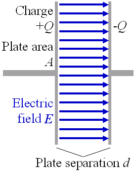
As for voltage, we’ve encountered that in previous posts. It’s a difference in potential indeed. Potential is that scalar number Φ which we associated with the potential energy U of a particle with charge q: Φ = U/q. So it’s like the potential energy of the unit charge, and we calculated by using the electric field vector to calculate the amount of work we needed to do to bring a unit charge to some point r: Φ(r) = –∫E·ds (the minus sign is there because we’re doing work against the electromagnetic force). We’ve actually calculated the difference in potential, or the voltage (difference) for something that’s called a capacitor: two parallel plates with a lack of electrons on one, and too many on the other (see below). As a result, there’s a strong electric field between both, and a difference in potential, and we’ve calculated the voltage as V = ΔΦ = σd/ε0 = qd/ε0A, with the d the plate separation (distance between the two plates), σ the (surface) charge per unit area, ε0 the electric constant and A the area of the plates. So it’s like a battery… For now at least–I’ll correct this statement later.
If we connect the two plates with a wire, i.e. a conductor, then we’ll have a current. Increasing the resistance of the circuit, by putting a resistor in, for example, will reduce the current and, hence, save the battery life somewhat. Of course, the resistor could be something that actually does work for us, a lamp, for example, or an electric motor.
Let me now correct that statement about a capacitor being like a battery. That statement is true and not true–but I must immediately add that it’s much more not true than true. 🙂 A battery is an active circuit element: it generates a voltage because of a chemical reaction that drives electrons through the circuit, and it will continue to provide power until all the reagents have been used up and the chemical reaction stops. In contrast, a capacitor is not active. There is a voltage only because charge has been stored on it (or, to be precise, because charges have been separated on it). Hence, when you connect the capacitor to a passive circuit, the current will only flow until all of the charge has been drained. So there’s no active element. Also, unlike a battery, the voltage on a capacitor is variable: it’s proportional to the amount of charge stored on it.
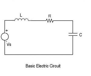
OK. So we’ve got a resistor, a capacitor and a voltage source, e.g. a battery but, because we want to look at resonance phenomena, we’ll not have a battery but a voltage source that drives the circuit with a nice sine wave oscillation. Why a sine wave? Well… First, it makes the mathematical analysis easier (we’ll have second-order differential equations again and so d2cosx/dt2 = –cosx and so that’s nice). Second, the AC current that comes into our houses is a nice sine wave indeed. So let’s put it all together now, including our AC generator (instead of a battery). The circuit can then be represented as follows:
In this circuit, the charge q on the capacitor is analogous to the displacement x of the mass on that oscillating spring we analyzed in the previous post. Likewise:
- I = dq/dt is analogous to the velocity v = dx/dt
- The resistance R is analogous to the resistive coefficient γ
- From our formula V = ΔΦ = σd/ε0, it is easy to see that V is proportional to the charge q: V = q/C, with 1/C the factor of proportionality, aka as the capacitance of the capacitor. In other words, 1/C is analogous to the spring constant k.
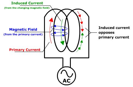
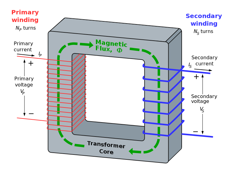
But we’re missing something: what’s the analogy to the mass or intertia factor in this circuit? Well… There’s one passive element in this circuit which we haven’t explained as yet: the self-inductance L. The phenomenon of self-inductance is the following: a changing electric current in a coil builds up a changing magnetic field, and that induces a current (and, hence, a voltage) that’s opposite to the primary current (and, hence, an opposite voltage). So it resists the change in current and, as such, it’s analogous to mass indeed. The illustration below explains how it works. I’ve also inserted a diagram showing how transformers work, because that’s based on the same principle of changing currents inducing changing magnetic fields that, in turn, generate another current. What’s going on in transformers is referred to as mutual inductance and note, indeed, that it doesn’t work with DC (i.e. steady) current.
Now, I know that’s not all that easy to understand, but I should limit myself here to just giving the formula: the induced voltage is such a coil is proportional to the time-rate of change of the current I = dq/dt. So we have a second-order derivative here:
V = LdI/dt = L(d2q/dt2)
So now we’re finally ready to put it all together. In that ‘basic electric circuit’ above, we’ve got the three passive circuit elements – resistor, capacitor and self-inductance – connected in series, and so then we apply a sine wave voltage to the whole circuit. Of course, all the voltages – i.e. over the resistor, over the capacitor, and over the self-inductance – must add up to the total voltage we apply to the circuit (which we’ll denote by V(t), as it’s a changing voltage), taking into account their sign. We have: VR = RI = R(dq/dt); VC = q/C; and VL = L(dI/dt) = L(d2q/dt2). Hence, we get:
L(d2q/dt2) + R(dq/dt) + q/C = V(t)
This is, once again, a differential equation of the second-order, and its mathematical form is the same as that equation for the oscillating spring (with a driving force and damping). [I repeat the equation below (in the section on the Q and the energy of an oscillator, so you don’t need to scroll too far.] So the solution is going to be the same and we’re going to have resonance if the angular frequency ω of our sine wave (i.e. the AC voltage generated by our generator) is close or equal to some kind of natural frequency characterizing the circuit. So what is that natural frequency ω0? Well… Just like ω02 was equal to k/m for our mechanical oscillator, we here get the grand result that ω02 = 1/LC, and our friction parameter γ corresponds to R/L.
The Q and the energy of an oscillator
There’s another point I did not develop in my previous post, and that was the energy of an oscillator. To explain that, we’ll take the example of our mechanical spring once again. The equation for that one was:
m(d2x/dt2) + γm(dx/dt) + mω02x = F(t)
Now, from my posts on energy concepts, you’ll remember that a force does work, and that the work done is the product of the force and the displacement (i.e. the distance over which the force is doing work). Work done is energy, potential or kinetic (one gets converted into the other). In addition, you may or may not remember that the work done per second gives us the power, so the concept of power relates energy to time, rather than distance.
For infinitesimal quantities (i.e. using differentials), we can write that the differential work done in a time dt is equal to F·dx. The power that’s expended by the force is then F·dx/dt, so that turns out to be the product of the force and the velocity (dx/dt = v): P = F·v. Now, if we substitute F for that differential equation above, and re-arrange the terms a bit, we get a fairly monstrously looking equation:
P = F·(dx/dt) = m[(d2x/dt2)(dx/dt) + ω02x(dx/dt)] + γm(dx/dt)2
Now it turns out that we can write the first two terms on the left on this monstrous equation as d/dt[m(dx/dt)2/2 + mω02x2/2]. So we have a time derivative here of a sum of two terms we recognize: the first is the kinetic energy (mv2/2) and the second (mω02x2/2) is the potential energy of the spring. [I would need to show that to you but I hope you believe me here.] Both of them taken together are the energy that’s stored in the oscillation, i.e. the stored energy. Now, in the long run, this driving force will not add any more energy to this quantity (the spring will oscillate back and forth, but so we’ll have stable motion and that’s it really). In other words, this derivative must be zero.
But so that driving force continues to do work and so the power must go somewhere. Where? It must all go to that other term: γm(dx/dt)2. What is that term? Well… It’s the energy that gets lost in friction: these are so-called resistive losses, and they usually get dissipated through heating. Hence, what happens is that most of the power of an external force is first used to build up the oscillation, thereby storing energy in the oscillator, but, once that’s done, the system only needs a little bit of energy to compensate for the heating (resistive) losses. Now the interesting thing is to calculate how much energy an oscillator can store. We can calculate that as follows:
- The energy carried by a physical wave is proportional to the square of its amplitude: E ∝ A2. Now, if it is a sinusoidal wave, we’ll need to take the average of the square of a sine or cosine function. Because sin2x and cos2x are the same functions really except for a phase difference of π/2, we can see that the average value for both functions should be 0.5 = 1/2. Hence, for any function Acosx, we can see that the average value of that square amplitude will be A2/2.
- From your statistics classes, you may also remember that the mean of a product of a variable and some constant (e.g. γm(dx/dt)2) will be equal to the product of that constant and the mean of the variable. So we can write 〈γm(dx/dt)2〉 = γm〈(dx/dt)2〉. Now, taking into account that the solution x for the differential equation is a cosine function x = x0cos(ωt+Δ), its derivative will also be a sinusoidal function but with ω in the amplitude as well. To make a long story short, 〈(dx/dt)2〉 is equal to ω2x02/2, and so we can write 〈γm(dx/dt)2〉 = γmω2x02/2.
- So the expression above gives the energy being absorbed by the oscillator on a permanent basis, and we’ll denote that by 〈P〉 = γmω2x02/2. How much energy is stored?
- Now that we’ve calculated 〈(dx/dt)2〉, we can calculate that too now. We’ll denote it by 〈E〉, and so 〈E〉 = 〈m(dx/dt)2/2 + mω02x2/2〉 = (1/2)m〈(dx/dt)2 + (1/2)mω02〈x2〉 = m(ω2 + ω02)x02/2. So what? Well… From the previous chapter, we know that x0 becomes very large if ω is near to ω0 (that’s what’s resonance is all about) and, hence, the stored energy will be quite large in that case. So the point is that we can get a large stored energy from a relatively small force, which is what you’d expect.
Now, the last thing I need to explain is the Q of an oscillator. The Q of an oscillator compares the stored energy with the amount of work that is done per cycle, multiplied by 2π for some historical reason I don’t understand to well:
Q = 2π·〈E〉/[〈P〉·2π/ω] = (ω2 + ω02)/2γω
Note that 2π/ω is the period, i.e. the time T0 that is needed to go through one cycle of the oscillation. As mentioned above, I am not sure about that 2π factor but it doesn’t matter too much: it’s just a constant and so we could divide by 2π and the result would not be substantially different: the Q is a relative number obviously, used to compare the efficiency of various oscillators when it comes to storing energy. Indeed, Q stands for quality: higher Q indicates a lower rate of energy loss relative to the stored energy of the resonator. So it implies that you do not need a lot of power to keep the oscillation going and, if the external driving force stops, that the oscillations will die out much more slowly. For example, a pendulum on a high-quality bearing, oscillating in air, will have a high Q, while a pendulum immersed in oil will have a low one.
But let me go back to the electric oscillator: we substitute m for L, R for mγ, and 1/C for mω02, and then we can see that, for ω = ω02 (so we calculate the Q at resonance), we find that Q = Lω/R, with ω the resonance frequency. Again, a circuit with high Q means that the circuit can store a very large amount of energy as compared to the work done per cycle of the voltage driving the oscillation.
An application of the Q: transients
Throughout this and my previous posts, I’ve managed to skirt around a more rigorous (i.e. mathematical) treatment of the subject-matter by not actually solving these second-order differential equations. So I won’t suddenly change tack and try to do that now. So this will, once again, be a rather intuitive approach. If you’d want a formal treatment, let me refer you to Paul’s Online Math Notes and, more in particular, the chapter on second-order DEs, which he wraps up with an overview of all differential equations you could possibly encounter when analyzing mechanical springs. But so here we go for the informal approach.
Above, we noted that the Q of a system is the ratio of (1) the stored energy (E) and (2) the work done per cycle, multiplied by 2π. Now, if we’d suddenly switch off the force, then no more work is being done, but the system will lose energy. Let’s suppose we have a system – an oscillating mechanical spring – for which we have a Q equal to 1000·2π, so we have Q/2π = 1000. So that means that the work done per cycle – when that driving force is still one – is one thousandth of its total energy. Hence, it’s not unreasonable to suggest that such system would also lose one thousandth of its total energy per cycle if we would just switch off the force and let go of it. Writing that assumption in terms of differential changes yields the following simple (first-order) differential equation:
dE/dt = –ωE/Q
Huh? Yes. Just think about it. A differential dE is associated with a differential dt. Now, the number of radians that the phase will go through during the infinitesimally short dt time interval is –ωdt, so the change in energy must be equal to dE = –ωdt·(E/Q) (the minus sign is there because we’re talking an energy loss obviously). So that gives us the equation above.
But what about ω? Well… If we just let that oscillator do what we would expect it to do, then it is not unreasonable to assume it would oscillate at its natural frequency. Hence, ω is likely to equal ω0. Combining these two assumptions (i.e. that differential equation above and the ω = ω0 assumption) gives us the following formula for E:
E = E0e–tω0 /Q = E0e–γt
[Note that γ is the same friction coefficient: Q = (ω2 + ω02)/2γω and, hence, if ω = ω0, then we get ω0/Q = γ indeed.]
Now, the energy goes as the square of the amplitude of the oscillation (i.e. the displacement x), so we would expect to find the square root of that e–γt in the solution for x, so that’s a e–γt/2 factor. If we’d formally solve it, we’d find the following solution for x indeed:
x = A0e–γt/2cos(ω0t + Δ)
The diagram below shows the envelope curve e–γt/2 as well as the x = e–γt/2cos(ω0t) curve (A0 and Δ depend on the initial conditions obviously). So that’s what’s called a transient: a solution of the differential equation when there is no force present.

Now, I could bombard you with even more equations, more concepts (like the concept of impedance indeed), but I won’t do that here. I hope this post managed to get the most important ideas across and, hence, I’ll conclude this mini-series (i.e. two successive posts) on resonance. As for my next post, I may be tempted to treat the topic of second-order differential equations more formally, that is from a purely mathematical perspective. But let’s see. 🙂
Post scriptum:
The idea of applying only a little bit of power to build up a large amounts of stored energy may or may not trigger some thoughts on how a photo flash works and, in fact, you’re right. A photo flash uses both a transformer (to step up voltage) as well as an oscillator circuit to store up energy. You can find the details on the Web. See, for example, http://electronics.howstuffworks.com/camera-flash3.htm 🙂
Some content on this page was disabled on June 16, 2020 as a result of a DMCA takedown notice from The California Institute of Technology. You can learn more about the DMCA here:

“The Q of an oscillator compares the stored energy with the amount of work that is done per cycle,…”
The denominator is, yes, the amount of work done per cycle, but 2pi appearing in the numerator become the denominator in “work per radians”.
The rational is given in Transient Chapter of Feynman Lectures, though 2Pi has to be removed from numerator eq 24.7 there, to actually corresponds with the explanation given in parenthesis there.