
My previous post was long and tedious, and all it did was presenting the three (passive) circuit elements as well as the concept of impedance. It show the inner workings of these little devices are actually quite complicated. Fortunately, the conclusions were very neat and short: for all circuit elements, we have a very simple relationship between (a) the voltage across the terminals of the element (V) and (b) the current that’s going through the circuit element (I). We found they are always in some ratio, which is referred to as the impedance, which we denoted by Z:
Z = V/I ⇔ V = I∗Z
So it’s a ‘simple’ ratio, indeed. But… Well… Simple and not simple. It’s a ratio of two complex numbers and, therefore, it’s a complex number itself. That’s why I use the ∗ symbol when re-writing the Z = V/I formula as V = I∗Z, so it’s clear we’re talking a product of two complex numbers). This ‘complexity’ is best understood by thinking of the voltage and the current as phase vectors (or phasors as engineers call them). Indeed, instead of using the sinusoidal functions we are used to, so that’s
- V = V0·cos(ωt + θV),
- I = I0·cos(ωt + θI), and
- Z = Z0·cos(ωt + θ) = (V0/I0)·cos(ωt + θV − θI),
we preferred the complex or vector notation, writing:
- V = |V|ei(ωt + θV) = V0·ei(ωt + θV)
- I = |I|ei(ωt + θI) = I0·ei(ωt + θI)
- Z = |ZIei(ωt + θ) = Z0·ei(ωt + θ) = (V0/I0)·ei(ωt + θV − θI)
For the three circuit elements, we found the following solution for Z in terms of the previously defined properties of the respective circuit elements, i.e. their resistance (R), capacitance (C), and inductance (L) respectively:
- For a resistor, we have Z(resistor) = ZR = R
- For an capacitor, we have Z(capacitor) = ZC = 1/iωC = –i/(ωC)
- For an inductor, we have Z(inductance) = ZL= iωL
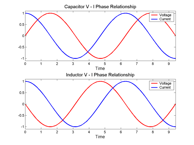
We also explained what these formulas meant, using graphs like the ones below:
- The graph on the left-hand side gives you the ratio of the peak voltage and peak current for the three devices as a function of C, L, R and ω respectively.
- The graph on the right-hand side shows you the relationship between the phase of the voltage and the current for a capacitor and for an inductor. [For a resistor, the phases are the same, so no need for a graph. Also note that the lag of the phase of the current vis-á-vis the voltage phase is 90 degrees for an inductor, while it’s 270 degrees for a capacitor (which amounts to the current leading the voltage with a 90° phase difference).]
The inner workings of our circuit elements are all wonderful and mysterious, and so we spent a lot of time writing about them. That’s finished now. The summary about describes all of them in very simple terms, relating the voltage and current phasor through the concept of impedance, which is just a ratio—albeit a complex ratio.
As the graphs above suggest, we can build all kinds of crazy circuits now, and the idea of resonance as we’ve learned it when studying the behavior of waves will be particularly relevant when discussing circuits that are designed to filter certain frequencies or, the opposite, to amplify some. We won’t go that far in this post, however, as I just want to explain the basic rules one needs to know when looking at a circuit, i.e. Kirchoff’s circuit laws. There are two of them:
1. Kirchoff’s Voltage Law (KCL): The sum of the voltage drops around any closed path is zero.
The principle is illustrated below. It doesn’t matter whether or not we have other circuits feeding into this one: Kirchoff’s Voltage Law (KCL) remains valid.

We can write this law using the concept of circulation once again or, what you’ll probably like more, just using plain summation:
2. Kirchoff’s Current Law (KCL): The sum of the currents into any node is zero.
This law is written and illustrated as follows:
![]()

This Law requires some definition of a node, of course. Feynman defines a node as any set of terminals such as a, b, c, d in the illustration above which are connected. So it’s a set of connected terminals.
Now, I’ll refer you Feynman for some practical examples. The circuit below is one of them. It looks complicated but it all boils down to solving a set of linear equations. So… Well… That’s it, really. We’re done! We should do the exercises, of course, but then we’re too lazy for that, I guess. 🙂 So we’re done!
Well… Almost. I also need to mention how one can reduce complicated circuits by combining parallel impedances, using the following formula:
![]()
And then another powerful idea is the idea of equivalent circuits. The rules for this are as follows:
- Any two-terminal network of passive elements is equivalent to (and, hence, can be replaced by) an effective impedance (Zeff).
- Any two-terminal network of passive elements is equivalent to (and, hence, can be replaced by) a generator in series with an impedance.
These two principles are illustrated below: (a) is equivalent to (b) in each diagram.
The related formulas are:
- I = Ɛ/Zeff
- Vn = Ɛeff − In∗Zeff
Last but not least, I need to say something about the energy in circuits. As we noted in our previous post, the impedance will consist of a real and an imaginary part. We write:
Z = R + i·X
This gives rise to the following powerful equivalence: any impedance is equivalent to a series combination of a pure resistance and a pure reactance, as illustrated below (the ≡ sign stands for equivalence):
Of course, because this post risks becoming too short 🙂 I need to insert some more formulas now. If Z = R + i·X is the impedance of the whole circuit, then the whole circuit can be summarized in the following equation:
Ɛ = I∗Z = I∗(R + i·X)
Now, if we bring the analysis back to the real parts of this equation, then we may write our current as I = I0·cos(ωt). This implies we chose a t = 0 point so θI = 0. [Note that this is somewhat different than what we usually do: we usually chose our t = 0 point such that θV = 0, but it doesn’t matter.] The real emf is then going to be the real part of Ɛ = I∗Z = I∗(R + i·X), so we’ll write it as Ɛ (no bold-face), and it’s going to be the real part of that expression above, which we can also write as:
Ɛ = I∗Z = I0·ei(ωt) ∗(R + i·X)
So Ɛ is the real part of this Ɛ and, you should check, it’s going to be equal to:
Ɛ = I0·R·cos(ωt) − I0·X·sin(ωt)
The two terms in this equation represent the voltage drops across the resistance R and the reactance X in that illustration above. […] Now that I think of it, in line with the -or and -ance convention for circuit elements and their properties, should we, perhaps, say resistor and reactor in this case? 🙂 […] OK. That’s a bad joke. [I don’t seem to have good ones, isn’t it?] 🙂
Jokes aside, we see that the voltage drop across the resistance is in phase with the current (because it’s a simple cosine function of ωt as well), while the voltage drop across the purely reactive part is out of phase with the current (as you know, the sine and cosine are the same function, but with a phase difference of π/2 indeed).
You’ll wonder where are we going with this, so let me wrap it all up. You know the power is the emf times the current, and so let’s integrate this thing over one cycle to get the average rate (and then I mean a time rate of change) of the energy that gets lost in the circuit. So we need to solve the following integral:
This may look like a monster, but if you look back at your notes from your math classes, you should be able to figure it out:
- The first integral is (1/2)I02·R..
- The second integral is zero.
So what? Well… Look at it! It means that the (average) energy loss in a circuit with impedance Z = R + i·X only depends on the real part of Z, which is equal to I02·R/2. That’s, of course, how we want it to be: ideal inductances and capacitors store energy when being powered, and give whatever they stored when ‘charging’ back to the circuit when the current reverses direction.
So it’s a nice result, because it’s consistent with everything. Hmm… Let’s double-check though… Is it also consistent with the power equation for a resistor which, remember, is written as: P = V·I = I·R·I = I2·R. […] Well… What about the 1/2 factor?
Well… Think about it. I is a sine or a cosine here, and so we want the average value of its square, so that’s 〈cos2(ωt)〉 = 1/2.
Done! 🙂
Some content on this page was disabled on June 16, 2020 as a result of a DMCA takedown notice from The California Institute of Technology. You can learn more about the DMCA here:
https://wordpress.com/support/copyright-and-the-dmca/
Some content on this page was disabled on June 16, 2020 as a result of a DMCA takedown notice from The California Institute of Technology. You can learn more about the DMCA here:https://wordpress.com/support/copyright-and-the-dmca/
Some content on this page was disabled on June 16, 2020 as a result of a DMCA takedown notice from The California Institute of Technology. You can learn more about the DMCA here:https://wordpress.com/support/copyright-and-the-dmca/
Some content on this page was disabled on June 16, 2020 as a result of a DMCA takedown notice from The California Institute of Technology. You can learn more about the DMCA here:https://wordpress.com/support/copyright-and-the-dmca/
Some content on this page was disabled on June 16, 2020 as a result of a DMCA takedown notice from The California Institute of Technology. You can learn more about the DMCA here:https://wordpress.com/support/copyright-and-the-dmca/
Some content on this page was disabled on June 16, 2020 as a result of a DMCA takedown notice from The California Institute of Technology. You can learn more about the DMCA here:https://wordpress.com/support/copyright-and-the-dmca/
Some content on this page was disabled on June 16, 2020 as a result of a DMCA takedown notice from The California Institute of Technology. You can learn more about the DMCA here:https://wordpress.com/support/copyright-and-the-dmca/
Some content on this page was disabled on June 16, 2020 as a result of a DMCA takedown notice from The California Institute of Technology. You can learn more about the DMCA here:https://wordpress.com/support/copyright-and-the-dmca/
Some content on this page was disabled on June 16, 2020 as a result of a DMCA takedown notice from The California Institute of Technology. You can learn more about the DMCA here:https://wordpress.com/support/copyright-and-the-dmca/
Some content on this page was disabled on June 17, 2020 as a result of a DMCA takedown notice from Michael A. Gottlieb, Rudolf Pfeiffer, and The California Institute of Technology. You can learn more about the DMCA here:https://wordpress.com/support/copyright-and-the-dmca/
Some content on this page was disabled on June 17, 2020 as a result of a DMCA takedown notice from Michael A. Gottlieb, Rudolf Pfeiffer, and The California Institute of Technology. You can learn more about the DMCA here:https://wordpress.com/support/copyright-and-the-dmca/
Some content on this page was disabled on June 20, 2020 as a result of a DMCA takedown notice from Michael A. Gottlieb, Rudolf Pfeiffer, and The California Institute of Technology. You can learn more about the DMCA here:
