
Pre-scriptum (dated 26 June 2020): This post – part of a series of rather simple posts on elementary math and physics – has suffered only a little bit from the attack by the dark force—which is good because I still like it. Only one or two illustrations were removed because of perceived ‘unfair use’, but you will be able to google equivalent stuff. While my views on the true nature of light, matter and the force or forces that act on them have evolved significantly as part of my explorations of a more realist (classical) explanation of quantum mechanics, I think most (if not all) of the analysis in this post remains valid and fun to read. Understanding the dynamics of rotations is extremely important in any realist interpretation of quantum physics. In fact, I would dare to say it is all about rotation!
Original post:
You know a gyroscope: it’s a spinning wheel or disk mounted in a frame that itself is free to alter in direction, so the axis of rotation is not affected as the mounting tilts or moves about. Therefore, gyroscopes are used to provide stability or maintain a reference direction in navigation systems. Understanding a gyroscope itself is simple enough: it only involves a good understanding of the so-called moment of inertia. Indeed, in the previous post, we introduced a lot of concepts related to rotational motion, notably the concepts of torque and angular momentum but, because that post was getting too long, I did not talk about the moment of inertia and gyroscopes. Let me do that now. However, I should warn you: you will not be able to understand this post if you haven’t read or didn’t understand the previous post. So, if you can’t follow, please go back: it’s probably because you didn’t get the other post.
The moment of inertia and angular momentum are related but not quite the same. Let’s first recapitulate angular momentum. Angular momentum is the equivalent of linear momentum for rotational motion:
- If we want to change the linear motion of an object, as measured by its momentum p = mv, we’ll need to apply a force. Changing the linear motion means changing either (a) the speed (v), i.e. the magnitude of the velocity vector v, (b) the direction, or (c) both. This is expressed in Newton’s Law, F = m(dv/dt), and so we note that the mass is just a factor of proportionality measuring the inertia to change.
- The same goes for angular momentum (denoted by L): if we want to change it, we’ll need to apply a force, or a torque as it’s referred to when talking rotational motion, and such torque can change either (a) L’s magnitude (L), (b) L’s direction or (c) both.
Just like linear momentum, angular momentum is also a product of two factors: the first factor is the angular velocity ω, and the second factor is the moment of inertia. The moment of inertia is denoted by I so we write L = Iω. But what is I? If we’re analyzing a rigid body (which is what we usually do), then it will be calculated as follows:

This is easy enough to understand: the inertia for turning will depend not just on the masses of all of the particles that make up the object, but also on their distance from the axis of rotation–and note that we need to square these distances. The L = Iω formula, combined with the formula for I above, explains why a spinning skater doing a ‘scratch spin’ speeds up tremendously when drawing in his or her arms and legs. Indeed, the total angular momentum has to remain the same, but I becomes much smaller as a result of that r2 factor in the formula. Hence, if I becomes smaller, then ω has to go up significantly in order to conserve angular momentum.
Finally, we note that angular momentum and linear momentum can be easily related through the following equation:
![]()
That’s all kids stuff. To understand gyroscopes, we’ll have to go beyond that and do some vector analysis. In the previous post, we explained that rotational motion is usually analyzed in terms of torques than forces, and we detailed the relations between force and torque. More in particular, we introduced a torque vector τ with the following components:
τ = (τyz, τzx, τxy) = (τx, τy, τz) with
τx = τyz = yFz – zFy
τy = τzx = zFx – xFz
τz = τxy = xFy – yFx.
We also noted that this torque vector could be written as a cross product of a radius vector and the force: τ = r×F. Finally, we also pointed out the relation between the x-, y- and z-components of the torque vector and the plane of rotation:
(1) τx = τyz is rotational motion about the x-axis (i.e. motion in the yz-plane)
(2) τy = τzx is rotational motion about the y-axis (i.e. motion in the zx plane)
(3) τz = τxy is rotational motion about the z-axis (i.e. motion in the xy-plane)
The angular momentum vector L will have the same direction as the torque vector, but it’s the cross product of the radius vector and the momentum vector: L = r×p. For clarity, I reproduce the animation I used in my previous post once again.
How do we get that cross vector product for L? We noted that τ (i.e. the Greek tau) = dL/dt. So we need to take the time derivative of all three components of L. What are the components of L? They look very similar to those of τ:
L = (Lyz, Lzx, Lxy) = (Lx, Ly, Lz) with
Lx = Lyz = ypz – zpy
Ly = Lzx = zpx – xpz
Lz = Lxy = xpy – ypx.
Now, just check the time derivatives of Lx, Ly, and Lz and you’ll find the components of the torque vector τ. Together with the formulas above, that should be sufficient to convince you that L is, indeed, a vector cross product of r and p: L = r×p.
Again, if you feel this is too difficult, please read or re-read my previous post. But if you do understand everything, then you are ready for a much more difficult analysis, and that’s an explanation of why a spinning top does not fall as it rotates about.
In order to understand that explanation, we’ll first analyze the situation below. It resembles the experiment with the swivel chair that’s often described on ‘easy physics’ websites: the man below holds a spinning wheel with its axis horizontal, and then turns this axis into the vertical. As a result, the man starts to turn himself in the opposite direction.

Let’s now look at the forces and torques involved. These are shown below.
This looks very complicated–you’ll say! You’re right: it is quite complicated–but not impossible to understand. First note the vectors involved in the starting position: we have an angular momentum vector L0 and an angular velocity vector ω0. These are both axial vectors, as I explained in my previous post: their direction is perpendicular to the plane of motion, i.e. they are arrows along the axis of rotation. This is in line with what we wrote above: if an object is rotating in the zx-plane (which is the case here), then the angular momentum vector will have a y-component only, and so it will be directed along the y-axis. Which side? That’s determined by the right-hand screw rule. [Again, please do read my previous post for more details if you’d need them.]
So now we have explained L0 and ω0. What about all the other vectors? First note that there would be no torque if the man would not try to turn the axis. In that case, the angular momentum would just remain what it is, i.e. dL/dt = 0, and there would be no torque. Indeed, remember that τ = dL/dt, just like F = dp/dt, so dL/dt = 0, then τ = 0. But so the man is turning the axis of rotation and, hence, τ = dL/dt ≠ 0. What’s changing here is not the magnitude of the angular momentum but its direction. As usual, the analysis is in terms of differentials.
As the man turns the spinning wheel, the directional change of the angular momentum is defined by the angle Δθ, and we get a new angular momentum vector L1. The difference between L1 and L0 is given by the vector ΔL. This ΔL vector is a tiny vector in the L0L1 plane and, because we’re looking at a differential displacement only, we can say that, for all practical purposes, this ΔL is orthogonal to L0 (as we move from L0 to L1, we’re actually moving along an arc and, hence, ΔL is a tangential vector). Therefore, simple trigonometry allows us to say that its magnitude ΔL will be equal to L0Δθ. [We should actually write sin(Δθ) but, because we’re talking differentials and measuring angles in radians (so the value reflects arc lengths), we can equate sin(Δθ) with Δθ).]
Now, the torque vector τ has the same direction as the ΔL vector (that’s obvious from their definitions), but what is its magnitude? That’s an easy question to answer: τ = ΔL/Δt = L0Δθ/Δt = L0 (Δθ/Δt). Now, this result induces us to define another axial vector which we’ll denote using the same Greek letter omega, but written as a capital letter instead of in lowercase: Ω. The direction of Ω is determined by using that right-hand screw rule which we’ve always been using, and Ω‘s magnitude is equal to Ω = Δθ/Δt. So, in short, Ω is an angular velocity vector just like ω: its magnitude is the speed with which the man is turning the axis of rotation of the spinning wheel, and its direction is determined using the same rules. If we do that, we get the rather remarkable result that we can write the torque vector τ as the cross product of Ω and L0:
τ = Ω×L0
Now, this is not an obvious result, so you should check it yourself. When doing that, you’ll note that the two vectors are orthogonal and so we have τ = Ω×L0 = Ω×L0 =|Ω||L0|sin(π/2)n = ΩL0n with n the normal unit vector given, once again, by the right-hand screw rule. [Note how the order of the two factors in a cross product matters: a×b = –b×a.]
You’re probably tired of this already, and so you’ll say: so what?
Well… We have a torque. A torque is produced by forces, and a torque vector along the z-axis is associated with rotation about the z-axis, i.e. rotation in the xy-plane. Such rotation is caused by the forces F and –F that produce the torque, as shown in the illustration. [Again, their direction is determined by the right-hand screw rule – but I’ll stop repeating that from now on.] But… Wait a minute. First, the direction is wrong, isn’t it? The man turns the other way in reality. And, second, where do these forces come from? Well… The man produces them, and the direction of the forces is not wrong: as the man applies these forces, with his hands, as he holds the spinning wheel and turns it into the vertical direction, equal and opposite forces act on him (cf. the action-reaction principle), and so he starts to turn in the opposite direction.
So there we are: we have explained this complex situation fully in terms of torques and forces now. So that’s good. [If you don’t believe the thing about those forces, just get one of your wheels out of your mountainbike, let it spin, and try to change the plane in which it is spinning: you’ll see you’ll need a bit of force. Not much, but enough, and it’s exactly the kind of force that the man in the illustration is experiencing.]
Now, what if we would not be holding the spinning wheel? What if we would let it pivot, for example? Well… It would just pivot, as shown below.
But… Why doesn’t it fall? Hah! There we are! Now we are finally ready for the analysis we really want to do, i.e. explaining why these spinning tops (or gyros as they’re referred to in physics) don’t fall.
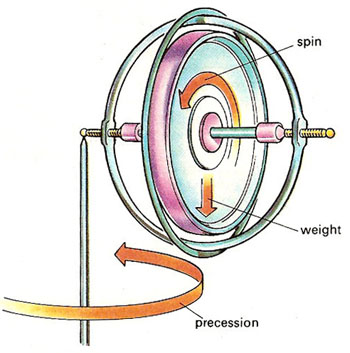
Such spinning top is shown in the illustration below. It’s similar to the spinning wheel: there’s a rotational axis, and we have the force of gravity trying to change the direction of that axis, so it’s like the man turning that spinning wheel indeed, but so now it’s gravity exerting the force that’s needed to change the angular momentum. Let’s associate the vertical direction with the z-axis, and the horizontal place with the xy-axis, and let’s go step-by-step:
- The gravitational force wants to pull that spinning top down. So the ΔL vector points downward this time, not upward. Hence, the torque vector will point downward too. But so it’s a torque pointing along the z-axis.
- Such torque along the z-axis is associated with a rotation in the xy-plane, so that’s why the spinning top will slowly revolve about the z-axis, parallel to the xy-plane. This process is referred to as precession, and so there’s a precession torque and a precession angular velocity.
So that explains precession and so that’s all there is to it. Now you’ll complain, and rightly so: what I write above, does not explain why the spinning top does not actually fall. I only explained that precession movement. So what’s going on? That spinning top should fall as it precesses, shouldn’t it?
It actually does fall. The point to note, however, is that the precession movement itself changes the direction of the angular momentum vector as well. So we have a new ΔL vector pointing sideways, i.e. a vector in the horizontal plane–so not along the z axis. Hence, we should have a torque in the horizontal plane, and so that implies that we should have two equal and opposite forces acting along the z-axis.
In fact, the right-hand screw rule gives us the direction of those forces: if these forces were effectively applied to the spinning top, it would fall even faster! However, the point to note is that there are no such forces. Indeed, it is not like the man with the spinning wheel: no one (or nothing) is pushing or applying the forces that should produce the torque associated with this change in angular momentum. Hence, because these forces are absent, the spinning top begins to ‘fall’ in the opposite direction of the lacking force, thereby counteracting the gravitational force in such a way that the spinning top just spins about the z-axis without actually falling.
Now, this is, most probably, very difficult to understand in the way you would like to understand it, so just let it sink in and think about it for a while. In this regard, and to help the understanding, it’s probably worth noting that the actual process of reaching equilibrium is somewhat messy. It is illustrated below: if we hold a spinning gyro for a while and then, suddenly, we let it fall (yes, just let it go), it will actually fall. However, as it’s falling, it also starts turning and then, because it starts turning, it also starts ‘falling’ upwards, as explained in that story of the ‘missing force’ above. Initially, the upward movement will overshoot the equilibrium position, thereby slowing the gyro’s speed in the horizontal plane. And so then, because its horizontal speed becomes smaller, it stops ‘falling upward’, and so that means it’s falling down again. But then it starts turning again, and so on and so on. I hope you grasp this–more or less at least. Note that frictional effects will cause the up-and-down movement to dampen out, and so we get a so-called cycloidal motion dampening down to the steady motion we associate with spinning tops and gyros.
That, then, is the ‘miracle’ of a spinning top explained. Is it less of a ‘miracle’ now that we have explained it in terms of torques and missing forces? That’s an appreciation which each of us has to make for him- or herself. I actually find it all even more wonderful now that I can explain it more or less using the kind of math I used above–but then you may have a different opinion.
In any case, let us – to wrap it all up – ask some simple questions about some other spinning objects. What about the Earth for example? It has an axis of rotation too, and it revolves around the Sun. Is there anything like precession going on?
The first answer is: no, not really. The axis of rotation of the Earth changes little with respect to the stars. Indeed, why would it change? Changing it would require a torque, and where would the required force for such torque come from? The Earth is not like a gyro on a pivot being pulled down by some force we cannot see. The Sun attracts the Earth as a whole indeed. It does not change its axis of rotation. That’s why we have a fairly regular day and night cycle.
The more precise answer is: yes, there actually is a very slow axial precession. The whole precessional cycle takes approximately 26,000 years, and it causes the position of stars – as perceived by us, earthlings, that is – to slowly change. Over this cycle, the Earth’s north axial pole moves from where it is now, in a circle with an angular radius of about 23.5 degrees, as illustrated below.
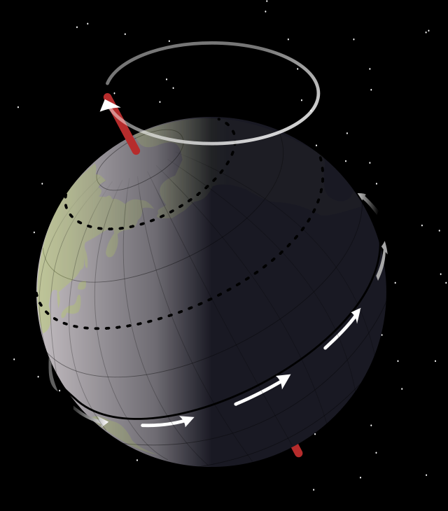
What is this precession caused by? There must be some torque. There is. The Earth is not perfectly spherical: it bulges outward at the equator, and the gravitational tidal forces of the Moon and Sun apply some torque here, attempting to pull the equatorial bulge into the plane of the ecliptic, but instead causing it to precess. So it’s a quite subtle motion, but it’s there, and it’s got also something to do with the gravitational force. However, it’s got nothing to do with the way gravitation makes a spinning top do what it does. [The most amazing thing about this, in my opinion, is that, despite the fact that the precessional movement is so tiny, the Greeks had already discovered it: indeed, the Greek astronomer and mathematician Hipparchus of Nicaea gave a pretty precise figure for this so-called ‘precession of the equinoxes’ in 127 BC.]
What about electrons? Are they like gyros rotating around some pivot? Here the answer is very simple and very straightforward: No, not at all! First, there are no pivots in an atom. Second, the current understanding of an electron – i.e. the quantum-mechanical understanding of a electron – is not compatible with the classical notion of spin. Let me just copy an explanation from Georgia State University’s HyperPhyics website. It basically says it all:
“Experimental evidence like the hydrogen fine structure and the Stern-Gerlach experiment suggest that an electron has an intrinsic angular momentum, independent of its orbital angular momentum. These experiments suggest just two possible states for this angular momentum, and following the pattern of quantized angular momentum, this requires an angular momentum quantum number of 1/2. With this evidence, we say that the electron has spin 1/2. An angular momentum and a magnetic moment could indeed arise from a spinning sphere of charge, but this classical picture cannot fit the size or quantized nature of the electron spin. The property called electron spin must be considered to be a quantum concept without detailed classical analogy.”
So… I guess this should conclude my exposé on rotational motion. I am not sure what I am going to write about next, but I’ll see. 🙂
Post scriptum:
The above treatment is largely based on Feynman’s Lectures.(Vol. I, Chapter 18, 19 and 20). The subject could also be discussed using the concept of a force couple, aka pure moment. A force couple is a system of forces with a resultant moment but no resultant force. Hence, it causes rotation without translation or, more generally, without any acceleration of the centre of mass. In such analysis, we can say that gravity produces a force couple on the spinning top. The two forces of this couple are equal and opposite, and they pull at opposite ends. However, because one end of the top is fixed (friction forces keep the tip fixed to the ground), the force at the other end makes the top go about the vertical axis.
The situation we have is that gravity causes such force couple to appear, just like the man tilting the spinning wheel causes such force couple to appear. Now, the analysis above shows that the direction of the new force is perpendicular to the plane in which the axis of rotation changes, or wants to change in the case of our spinning top. So gravity wants to pull the top down and causes it to move sideways. This horizontal movement will, in turn, create another force couple. The direction of the resultant force, at the free end of the axis of rotation of the top, will, once again, be vertical, but it will oppose the gravity force. So, in a very simplified explanation of things, we could say:
- Gravity pulls the top downwards, and causes a force that will make the top move sideways. So the new force, which causes the precession movement, is orthogonal to the gravitation force, i.e. it’s a horizontal force.
- That horizontal force will, in turn, cause another force to appear. That force will also be orthogonal to the horizontal force. As we made two 90 degrees turns, so to say, i.e. 180 degrees in total, it means that this third force will be opposite to the gravitational force.
- In equilibrium, we have three forces: gravity, the force causing the precession and, finally, a force neutralizing gravity as the spinning top precesses about the vertical axis.
This approach allows for a treatment that is somewhat more intuitive than Feynman’s concept of the ‘missing force.’
Some content on this page was disabled on June 16, 2020 as a result of a DMCA takedown notice from The California Institute of Technology. You can learn more about the DMCA here:
https://wordpress.com/support/copyright-and-the-dmca/
Some content on this page was disabled on June 16, 2020 as a result of a DMCA takedown notice from The California Institute of Technology. You can learn more about the DMCA here:https://wordpress.com/support/copyright-and-the-dmca/
Some content on this page was disabled on June 16, 2020 as a result of a DMCA takedown notice from The California Institute of Technology. You can learn more about the DMCA here:https://wordpress.com/support/copyright-and-the-dmca/
Some content on this page was disabled on June 16, 2020 as a result of a DMCA takedown notice from The California Institute of Technology. You can learn more about the DMCA here:

About Feynman’s insight that the gyroscope must dip in order to start precessing at all:
In 2010 Svilen Kostov and Daniel Hammer have set up an experiment to confirm Feynman’s assessment. They report excellent agreement.
Click to access Feynman%20gyroscope%20article%20in%20TPT.pdf
In lecture demonstrations the gyroscope wheel is always released gingerly. In effect the demonstrator applies damping, preventing any nutation.
A simpler explanation is possible in the following case:
– precession rate much slower than the spin rate
– spin axis perpendicular to precession axis
That case is explained in the article about Gyroscopes on my website:
http://www.cleonis.nl/physics/phys256/gyroscope_physics.php
The symmetry of the setup (perpendicular axes) allows an explanation that doesn’t involve the spin angular momentum of the gyroscope wheel.
Of course the general case does require the general analysis that you present above.
Incidentally, on gyroscope explanations in general, I noticed several wrong “explanations” on the web. They go something like this: “The top of the wheel experiences a force, and after the wheel has turned 90 degrees the wheel remembers that, and it moves accordingly.” Or (talking about helicopter rotors) “There is a 90 degrees phase shift in the response.” Obviously such delayed response “explanations” make no sense, that’s not how dynamics works.
I do not even know how I finished up right here, but I
assumed this put up was good. I don’t understand who you might be however definitely you are going to a well-known blogger in case you are not already.
Cheers!