
We studied the magnetic dipole in very much detail in one of my previous posts but, while we talked about an awful lot of stuff there, we actually managed to not talk about the torque on a it, when it’s placed in the magnetic field of other currents, or some other magnetic field tout court. Now, that’s what drives electric motors and generators, of course, and so we should talk about it, which is what I’ll do here. Let me first remind you of the concept of torque, and then we’ll apply it to a loop of current. 🙂
The concept of torque
The concept of torque is easy to grasp intuitively, but the math involved is not so easy. Let me sum up the basics (for the detail, I’ll refer you to my posts on spin and angular momentum). In essence, for rotations in space (i.e. rotational motion), the torque is what the force is for linear motion:
- It’s the torque (τ) that makes an object spin faster or slower around some axis, just like the force would accelerate or decelerate that very same object when it would be moving along some curve.
- There’s also a similar ‘law of Newton’ for torque: you’ll remember that the force equals the time rate of change of a vector quantity referred to as (linear) momentum: F = dp/dt = d(mv)/dt = ma (the mass times the acceleration). Likewise, we have a vector quantity that is referred to as angular momentum (L), and we can write: τ (i.e. the Greek tau) = dL/dt.
- Finally, instead of linear velocity, we’ll have an angular velocity ω (omega), which is the time rate of change of the angle θ that defines how far the object has gone around (as opposed to the distance in linear dynamics, describing how far the object has gone along). So we have ω = dθ/dt. This is actually easy to visualize because we know that θ, expressed in radians, is actually the length of the corresponding arc on the unit circle. Hence, the equivalence with the linear distance traveled is easily ascertained.
There are many more similarities, like an angular acceleration: α = dω/dt = d2θ/dt2, and we should also note that, just like the force, the torque is doing work – in its conventional definition as used in physics – as it turns an object instead of just moving it, so we can write:
ΔW = τ·Δθ
So it’s all the same-same but different once more 🙂 and so now we also need to point out some differences. The animation below does that very well, as it relates the ‘new’ concepts – i.e. torque and angular momentum – to the ‘old’ concepts – i.e. force and linear momentum. It does so using the vector cross product, which is really all you need to understand the math involved. Just look carefully at all of the vectors involved, which you can identify by their colors, i.e. red-brown (r), light-blue (τ), dark-blue (F), light-green (L), and dark-green (p).
So what do we have here? We have vector quantities once again, denoted by symbols in bold-face. Having said that, I should note that τ, L and ω are ‘special’ vectors: they are referred to as axial vectors, as opposed to the polar vectors F, p and v. To put it simply: polar vectors represent something physical, and axial vectors are more like mathematical vectors, but that’s a very imprecise and, hence, essential non-correct definition. 🙂 Axial vectors are directed along the axis of spin – so that is, strangely enough, at right angles to the direction of spin, or perpendicular to the ‘plane of the twist’ as Feynman calls it – and the direction of the axial vector is determined by a convention which is referred to as the ‘right-hand screw rule’. 🙂
Now, I know it’s not so easy to visualize vector cross products, so it may help to first think of torque (also known, for some obscure reason, as the moment of the force) as a twist on an object or a plane. Indeed, the torque’s magnitude can be defined in another way: it’s equal to the tangential component of the force, i.e. F·sin(Δθ), times the distance between the object and the axis of rotation (we’ll denote this distance by r). This quantity is also equal to the product of the magnitude of the force itself and the length of the so-called lever arm, i.e. the perpendicular distance from the axis to the line of action of the force (this lever arm length is denoted by r0). So, we can define τ without the use of the vector cross-product, and in not less than three different ways actually. Indeed, the torque is equal to:
- The product of the tangential component of the force times the distance r: τ = r·Ft= r·F·sin(Δθ);
- The product of the length of the lever arm times the force: τ = r0·F;
- The work done per unit of distance traveled: τ = ΔW/Δθ or τ = dW/dθ in the limit.
Phew! Yeah. I know. It’s not so easy… However, I regret to have to inform you that you’ll need to go even further in your understanding of torque. More specifically, you really need to understand why and how we define the torque as a vector cross product, and so please do check out that post of mine on the fundamentals of ‘torque math’. If you don’t want to do that, then just try to remember the definition of torque as an axial vector, which is:
τ = (τyz, τzx, τxy) = (τx, τy, τz) with
τx = τyz = yFz – zFy (i.e. the torque about the x-axis, i.e. in the yz-plane),
τy = τzx = zFx – xFz (i.e. the torque about the y-axis, i.e. in the zx-plane), and
τz = τxy = xFy – yFx (i.e. the torque about the z-axis, i.e. in the xy-plane).
The angular momentum L is defined in the same way:
L = (Lyz, Lzx, Lxy) = (Lx, Ly, Lz) with
Lx = Lyz = ypz – zpy (i.e. the angular momentum about the x-axis),
Ly = Lzx = zpx – xpz (i.e. the angular momentum about the y-axis), and
Lz = Lxy = xpy – ypx (i.e. the angular momentum about the z-axis).
Let’s now apply the concepts to a loop of current.
The forces on a current loop
The geometry of the situation is depicted below. I know it looks messy but let me help you identifying the moving parts, so to speak. 🙂 We’ve got a loop with current and so we’ve got a magnetic dipole with some moment μ. From my post on the magnetic dipole, you know that μ‘s magnitude is equal to |μ| = μ = (current)·(area of the loop) = I·a·b.
Now look at the B vectors, i.e. the magnetic field. Please note that these vectors represent some external magnetic field! So it’s not like what we did in our post on the dipole: we’re not looking at the magnetic field caused by our loop, but at how it behaves in some external magnetic field. Now, because it’s kinda convenient to analyze, we assume that the direction of our external field B is the direction of the z-axis, so that’s what you see in this illustration: the B vectors all point north. Now look at the force vectors, remembering that the magnetic force is equal to:
Fmagnetic = qv×B
So that gives the F1, F2, F3, and F4 vectors (so that’s the force on the first, second, third and fourth leg of the loop respectively) the magnitude and direction they’re having. Now, it’s easy to see that the opposite forces, i.e. the F1–F2 and F3–F4 pair respectively, create a torque. The torque because of F1 and F2 is a torque which will tend to rotate the loop about the y-axis, so that’s a torque in the xz-plane, while the torque because of F3 and F4 will be some torque about the x-axis and/or the z-axis. As you can see, the torque is such that it will try to line up the moment vector μ with the magnetic field B. In fact, the geometry of the situation above is such that F3 and F4 have already done their job, so to speak: the moment vector μ is already lined up with the xz-plane, so there’s not net torque in that plane. However, that’s just because of the specifics of the situation here: the more general situation is that we’d have some torque about all three axes, and so we need to find that vector τ.
If we’d be talking some electric dipole, the analysis would be very straightforward, because the electric force is just Felectric = qE, which we can also write as E = Felectric =/q, so the field is just the force on one unit of electric charge, and so it’s (relatively) easy to see that we’d get the following formula for the torque vector:
τ = p×E
Of course, the p is the electric dipole moment here, not some linear momentum. [And, yes, please do try to check this formula. Sorry I can’t elaborate on it, but the objective of this blog is not substitute for a textbook!]
Now, all of the analogies between the electric and magnetic dipole field, which we explored in the above-mentioned post of mine, would tend to make us think that we can write τ here as:
τ = μ×B
Well… Yes. It works. Now you may want to know why it works 🙂 and so let me give you the following hint. Each charge in a wire feels that Fmagnetic = qv×B force, so the total magnetic force on some volume ΔV, which I’ll denote by ΔF for a while, is the sum of the forces on all of the individual charges. So let’s assume we’ve got N charges per unit volume, then we’ve got N·ΔV charges in our little volume ΔV, so we write: ΔF = N·ΔV·q·v×B. You’re probably confused now: what’s the v here? It’s the (drift) velocity of the (free) electrons that make up our current I. Indeed, the protons don’t move. 🙂 So N·q·v is just the current density j, so we get: ΔF = j×BΔV, which implies that the force per unit volume is equal to j×B. But we need to relate it to the current in our wire, not the current density. Relax. We’re almost there. The ΔV in a wire is just its cross-sectional area A times some length, which I’ll denote by ΔL, so ΔF = j×BΔV becomes ΔF = j×BAΔL. Now, jA is the vector current I, so we get the simple result we need here: ΔF = I×BΔL, i.e. the magnetic force per unit length on a wire is equal to ΔF/ΔL = I×B.
Let’s now get back to our magnetic dipole and calculate F1 and F2. The length of ‘wire’ is the length of the leg of the loop, i.e. b, so we can write:
F1 = −F2 = b·I×B
So the magnitude of these forces is equal F1 = F2 = I·B·b. Now, The length of the moment or lever arm is, obviously, equal to a·sinθ, so the magnitude of the torque is equal to the force times the lever arm (cf. the τ = r0·F formula above) and so we can write:
τ = I·B·b·a·sinθ
But I·a·b is the magnitude of the magnetic moment μ, so we get:
τ = μ·B·sinθ
Now that’s consistent with the definition of the vector cross product:
τ = μ×B = |μ|·|B|·sinθ·n = μ·B·sinθ·n
Done! Now, electric motors and generators are all about work and, therefore, we also need to briefly talk about energy here.
The energy of a magnetic dipole
Let me remind you that we could also write the torque as the work done per unit of distance traveled, i.e. as τ = ΔW/Δθ or τ = dW/dθ in the limit. Now, the torque tries to line up the moment with the field, and so the energy will be lowest when μ and B are parallel, so we need to throw in a minus sign when writing:
τ = −dU/dθ ⇔ dU = −τ·dθ
We should now integrate over the [0, θ] interval to find U, also using our τ = μ·B·sinθ formula. That’s easy, because we know that d(cosθ)/dθ = −sinθ, so that integral yields:
U = 1 − μ·B·cosθ + a constant
If we choose the constant to be zero, and if we equate μ·B with 1, we get the blue graph below:
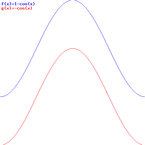
The μ·B in the U = 1 − μ·B·cosθ formula is just a scaling factor, obviously, so it determines the minimum and maximum energy. Now, you may want to limit the relevant range of θ to [0, π], but that’s not necessary: the energy of our loop of current does go up and down as shown in the graph. Just think about it: it all makes perfect sense!
Now, there is, of course, more energy in the loop than this U energy because energy is needed to maintain the current in the loop, and so we didn’t talk about that here. Therefore, we’ll qualify this ‘energy’ and call it the mechanical energy, which we’ll abbreviate by Umech. In addition, we could, and will, choose some other constant of integration, so that amounts to choosing some other reference point for the lowest energy level. Why? Because it then allows us to write Umech as a vector dot product, so we get:
Umech = −μ·B·cosθ = −μ·B
The graph is pretty much the same, but it now goes from −μ·B to +μ·B, as shown by the red graph in the illustration above.
Finally, you should note that the Umech = −μ·B formula is similar to what you’ll usually see written for the energy of an electric dipole: U = −p·E. So that’s all nice and good! However, you should remember that the electrostatic energy of an electric dipole (i.e. two opposite charges separated by some distance d) is all of the energy, as we don’t need to maintain some current to create the dipole moment!
Now, Feynman does all kinds of things with these formulas in his Lectures on electromagnetism but I really think this is all you need to know about it—for the moment, at least. 🙂

5 thoughts on “Magnetic dipoles and their torque and energy”